 br76530067
commented
3 years ago
br76530067
commented
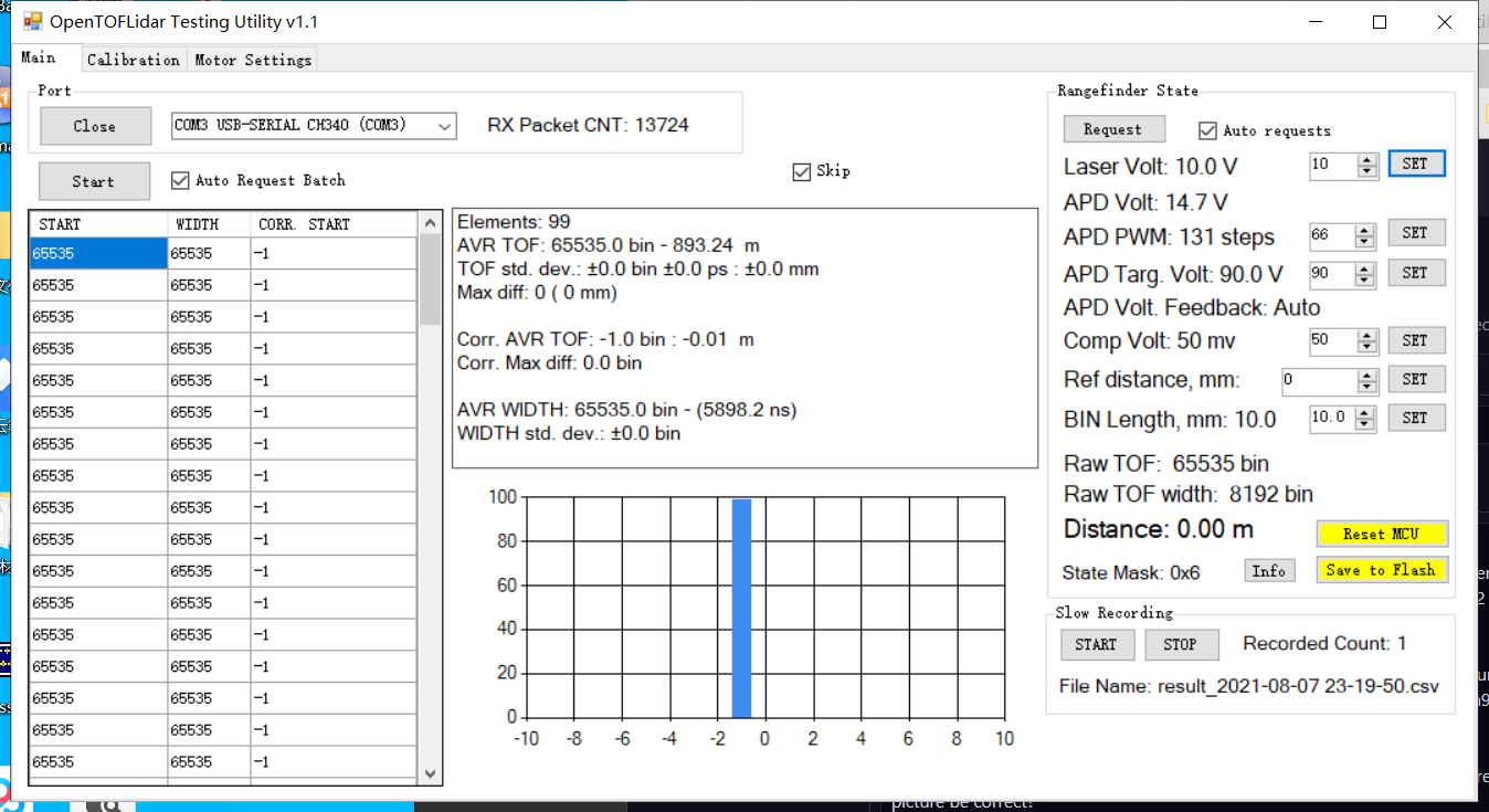
3 years ago And I can change the J2 signal by changing the Laser Volt on PC Testing Utility
Closed br76530067 closed 3 years ago
br76530067
commented
3 years ago And I can change the J2 signal by changing the Laser Volt on PC Testing Utility
br76530067
commented
3 years ago When set to 19V:


br76530067
commented
3 years ago Ok thanks, I use a Huawei phone to get the laser light successfully, pls omit the laser light problem.

 iliasam
commented
3 years ago
iliasam
commented
3 years ago And yes, laser is infrared, so different phones haw different IR filters. Best way is to use camera with no IR filters (like CCTV). Using 0.3 Ohm is not good idea - you will lose too much voltage at it (~4.5V). You can try to connect 3 resistors 0.3 Ohm parallel to get 0.1 Ohm, but I'm not sure how this will work (because of parasitic inductance of resistors). Be careful with laser voltage - high voltage can damage laser!
How you are connecting oscilloscope to the board? The best way is to use U.FL - BNC cable. Also it is possible to take coaxial cable with BNC connector and solder it instead of U.FL connectors at PCB. If you are using oscilloscope probe, you must use "oscilloscope ground spring": https://electronics.stackexchange.com/questions/40420/what-is-the-name-of-this-springy-type-oscilloscope-probe-accessory Otherwise you would see a lot of oscillations.
br76530067
commented
3 years ago Yes, U.FL - BNC cable


And I do not know why there will be a lot of oscillations, is it due to the inductance of the 0.3R resistor?

iliasam
commented
3 years ago Yes, using leaded resistor is not good at all. Also is your oscilloscope have an ability to switch its input impedance to 50 Ohm, you should use it.
br76530067
commented
3 years ago Ok, and I will replace the leaded resistor with a 0.1Ohm resistor with a 1206 footprint.

br76530067
commented
3 years ago But I saw this 0.1Ohm resistor also is Leaded resistor, could you recommend a type of resistor for me to buy and replce? Thanks
iliasam
commented
3 years ago As you can see in BOM, you need 0805 (2012 metric) 0.1 Ohm resistor.
br76530067
commented
3 years ago Ok, Thanks!
br76530067
commented
3 years ago Hi, Iliasam,
I replaced the 0.3Ohm lead resister with 0.1Ohm with 0805 footprints ( the type of this resister is 0.1Ohm, however, what I scale it by multimeter is 0.3Ohm). And I got the following pictures, should these pictures be correct? The laser voltage should be 10V because I haven't connected it to the PC to configure.


iliasam
commented
3 years ago For me this picture is too strange, signal should not be such oscillating, but I can't really remember exact waveforms at low voltage. But the first pulse must be highest one, as I can remember. Soldering flux should be removed from PCB (laser circuit). I can see that you have modified PCB comparing to my PCB, also I don't know what are the components that you are installed.
br76530067
commented
3 years ago Hi, Iliasam, thank you for your replying. I haven't changed your PCB, I just add a MEMS mirror driver part to your PCB, because I want to use the MEMS mirror to replace the rotating mirror in your project, and I am willing to share with you all of this project and I will open this after finishing. Maybe you are interested in it if so I could share with you some work I did( but I only do a little...)
And I found the following picture after I use the probe instead of the U.FL - BNC cable.
br76530067
commented
3 years ago 


iliasam
commented
3 years ago This is looking better, but pulse width seems too big for me. It is strange, that probe give better shape, that a special cable. You can try to change C17 to a smaller value to decrease pulse width. Could you say your full laser marking? Are you you using probe in x10 mode?
iliasam
commented
3 years ago I have added laser current screenshots from my oscilloscope (made with different voltages): https://github.com/iliasam/OpenTOFLidar/tree/develop/Images/Oscilloscope/LaserCurrent These measurements are made with UFL cable, oscilloscope input is in high-impedance mode.
br76530067
commented
3 years ago Hi, Iliasam,
At 10V:


At 11V:


Sorry, what do you exactly mean?
No, I am in X1 mode.
Thanks!
br76530067
commented
3 years ago 
iliasam
commented
3 years ago Now shape of the pulses is looking better, but pulse width is still ~50ns, while my pulse width was ~25 ns at 12V. Maybe you need to decrease C17 more.
" About: Could you say your full laser marking? Sorry, what do you exactly mean?" I mean full name of your laser diode. I'm using "SPL PL90_3", number 3 is important.
As I know, it is not recommended to use x1 mode for measuring high frequencies: http://electronics-diy.com/electronic_schematic.php?id=970
"#4 and do you know why there is the signal?" It is some kind of spike at the end (falling edge) of controlling pulse "LASER_PULSE" which is 1 us long. It is now visible at my oscillograms because they are too short. It is OK.
br76530067
commented
3 years ago Hi I am also using "SPL PL90_3"

iliasam
commented
3 years ago OK, I was afraid that you are using another type of laser.
br76530067
commented
3 years ago After changing C17 to 3.3 UF ,I got :
10V:

12V:

iliasam
commented
3 years ago Ok, this is looking better, so I think that electronics is working OK now. You can try to increase laser voltage to 14-15V. It would be good to get somehow the same pictures with UFL wire.
Hi, iliasam, I am working on step #4Install MOSFET, Laser diode, diode D7, and other lasers components. Check that laser is working by the camera. Do not look to the laser!! Check laser current pulses by connecting J2 to the oscilloscope. Current must change with changing "Vlaser".
however, I can not see the laser light on my iPhone camera, how do I make sure that is working?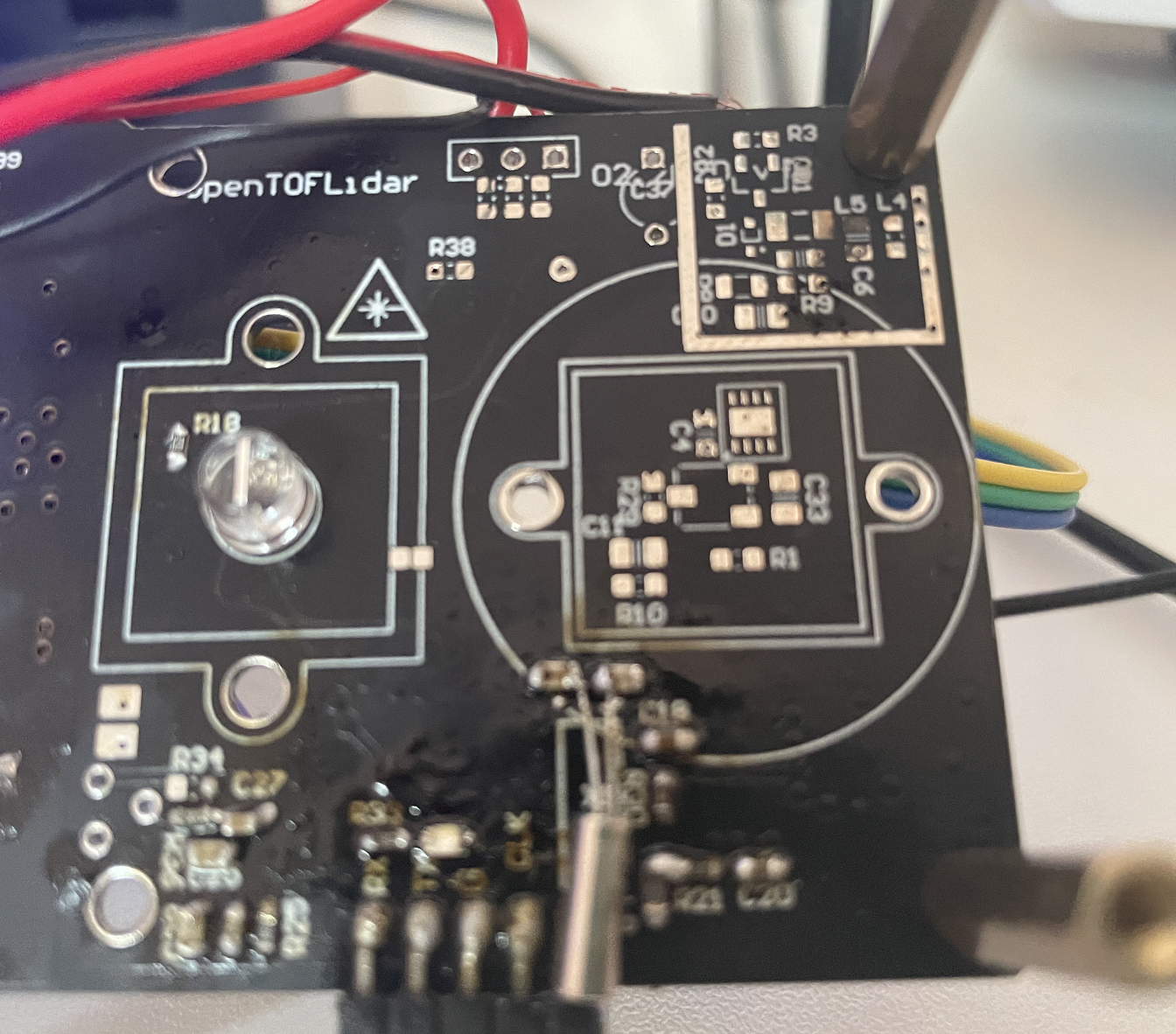
And I get the J2 oscilloscope picture like below ( because I do not have 0.1R resistance, so I use a 0.3R one), does the blow picture be correct?

Thanks in advance!