indrekluuk / LiveOV7670

A step-by-step guide to building the circuit for this project:
https://circuitjournal.com/arduino-ov7670-10fps
237 stars 91 forks source link

Can I have the PCB? #7

Open kareemramd opened 6 years ago

kareemramd commented 6 years ago

Hello sir,

I found your project on youtube and thats so incredible! But the wiring is to complicated, can you share the PCB scheme? Thank you!

indrekluuk commented 6 years ago

Hey!

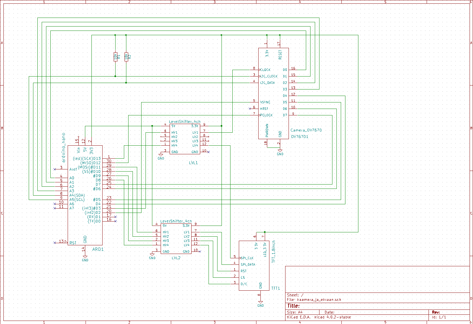
KiCAD project for the PCB is in the "pcb/kaamera_ja_ekraan/" folder of the LiveOV7670 repository: https://github.com/indrekluuk/LiveOV7670/tree/master/pcb/kaamera_ja_ekraan

If you want to order the PCB from OSH Park or from one of the Chinese manufacturers you can zip the "gerber" folder and upload it to the manufacturer's website.

kareemramd commented 6 years ago

Hey thank you sir!

Im sorry, i have zero knowledge about electronic. This is really help me!

larsenglund commented 6 years ago

I have a couple of pcbs left over that i can send if you pay for shipping..

kareemramd commented 6 years ago

@larsenglund : Nah im okey dude, beside I live in indonesia, the sipping cost is more expensive than the pcb itself. Thank you for offering me a help tho :)

indrekluuk commented 6 years ago

You also need to order two of those 4-channel level shifters: https://www.ebay.com/itm/1-2-5pcs-I2C-IIC-4-Channel-Logic-Level-Converter-Module-Bi-Directional-Arduino/112786869135?var=413225612516&_trkparms=aid%3D222007%26algo%3DSIM.MBE%26ao%3D2%26asc%3D49917%26meid%3Dd6a51c4e7ee34f3c8d4315d1f978c733%26pid%3D100005%26rk%3D6%26rkt%3D6%26sd%3D152383209372%26itm%3D413225612516&_trksid=p2047675.c100005.m1851

The PCB is designed to have two 10k surface mount (SMD 1206) resistors (you probably could solder through hole resistors on it sideways if you don't have surface mount resistors): https://www.ebay.com/itm/200PCS-Resistance-10K-10-000-ohm-Resistor-Mark-103-SMD-1206-3216-TOL-5-2432/302483919472?hash=item466d725270:g:BOoAAOSw-4BXa1gz

It is also good idea to orders these things so you do not have to solder the camera, arduino and the screen directly to the PCB: https://www.ebay.com/itm/10PCS-Male-Female-40pin-2-54mm-Header-Socket-Single-Row-Strip-PCB-Connector-Cool/311989222547?hash=item48a401bc93:m:m--pCbJTil9tJPnsrpDLEqg

kareemramd commented 6 years ago

Hello!

Thank you very much sir, this project really educating me. I watch your tutorial video and i think the video already give a specific step.

Now i know thats R1 and R2 is a resistor. Do you think the service manufacture will mount it for me? Or i need to do it by myself?

There's a few electronic shop and service manufacture around tho. So im okay this far. Maybe i'll update my project to you if you want but i dont know when (pretty busy with college hehe). I already told you that i want to make rearview camera for my helmet like the pict below.

HUD Helmet scheme

Big thanks sir.

Regards, Kareemramd

indrekluuk commented 6 years ago

You have to solder the components yourself. There are not that much so solder.

It only makes sense to order the PCBs with soldering by the manufacturer if you want to order thousands or tens of thousands of them.

The PCB is not exactly the same as in the tutorial video. Here the level shifters do the 5v to 3.3v conversion instead of the voltage dividers in the tutorial video. The two resistor required are for the i2c connection. This is the schematic for the PCB: https://raw.githubusercontent.com/indrekluuk/LiveOV7670/master/LiveOV7670.png

You have really ambitious project. It would be interesting to see how it turns out. You probably should design your own PCB in the end so you can design it to fit in the casing. But for initial prototyping by board will probably do.