jdesbonnet / RCWL-0516

Information about RCWL-0516 microwave proximity switch module (ICStation.com SKU 10630)
724 stars 104 forks source link

False triggers #2

Open mariusb57 opened 7 years ago

mariusb57 commented 7 years ago

I used this sensor with a esp8266 and i have a lot of false triggers. Seems to be strongly affect by the wireless network , in general , by strong electromagnetic fields . I tried to place him at a considerable distance from esp8266 and I used a lot of decoupling capacitors. Sure that the false switching operations were far fewer . I would like to know if anyone met this problem and how to solve it . If I mount a metalic shield on the back of the sensor, may this affect its detection properties ? Thanks .

ym58 commented 7 years ago

I've been struggling for WEEKS with a miniature DIY motion detector device built with RCWL-0516 + ESP8266 + mini 5V P/S. It sometimes works flawlessly for hours then starts giving false triggers repetitively ... I even tried to get the radar sensor out of the casing in case it would work better when distant from the ESP, but to no avail :-( I think this sensor is definitely prone to interferences and not reliable enough to be used in a motion detector device in the long run. The only thing I haven't tried yet is to use a strong capacitor across the VCC input of the radar sensor, but I doubt it will help ...

underwoodblog commented 7 years ago

Maby an isolated DC-DC converter can help to remove the interferences that come from the ESP to the RCWL over the supply voltage. I suggest some ferrites on the data and power cables to!

ym58 commented 7 years ago

Good point. The P/S I am using right now is this one : http://www.ebay.fr/itm/401301418281 I'll try to power it thru my lab P/S for testing purposes and will come back here to comment the results. Thanks.

mariusb57 commented 7 years ago

I think I found a solution. I just use the electrical source from the above link but without mounting a filter it does not work properly. I used a pi filter (1000 microfarad +10 ohm + 1000 microfarad) mounted on the sensor supply (Vin). Of course, if there are "parasite generators" around the sensor, such as mechanical relays or mechanical switches, false flashes may occur. I use it with a ESP 8266, and a SSR G3MB-202 that has its own snubbering circuit and at its command sometimes false flashes occur . I have solved these problems in the software by temporarily disabling the pin to which the sensor is bound.

ym58 commented 7 years ago

Mine is undertest since yesterday with a single 1000uF capacitor directly soldered on the Vin input. The false flashes have considerably reduced but not totally disappeared. I don't currently have any relay nor switching devices in my circuitry. Is this the way you wired your Pi-filter ? https://www.dropbox.com/s/9bth6k8vvs6nznv/RCWL-0516.jpg?raw=1 rcwl-0516

mariusb57 commented 7 years ago

Yes this is the configuration I've used .

ym58 commented 7 years ago

A bit of update :: I tried to power my device with my lab P/S. No significative improvement, still having (random) false triggers. Then, yesterday, I reconnected my 1USD-Chinese power supply ( http://www.ebay.fr/itm/401301418281 ) but I used mariusb57's pi-filter (see above) between Vin and Vcc .... so far, so good ! I'll carry on with the testing for another 48hrs and will keep you all posted.

ym58 commented 7 years ago

So far, soooooooooooooo good !!!!

The pi-filter (thanks to Mariusb57) works like a charm : I never had any more false triggers since I installed it between Vcc (+5V) and the Vin input of RCWL-0516 sensor !

I wish I could now understand the exact way this 'resistor-only' pi-filter works as (normally) a pi-filter is made up of an inductor instead of a resistor ... any clue ?

mariusb57 commented 7 years ago

The pi filter is not my merit, I have read this : http://tech.scargill.net/microwave-for-the-weekend/...... and I have made experiences for several days....

ym58 commented 7 years ago

I was a bit mistaken as it does not work THAT good.


Actually, as soon as I REcase the whole thing together (ESP + RCWL + P/S), it starts giving me again false triggers, particularly when the sensor stands very close to the ESP32E ... it's just disappointing for I wanted to make the whole device dense and compact.


If I can't get rid of those interferences between the ESP and the sensor, I will definitely have to rethink my layout and keep the RCWL-0516 outside of the casing as I confirm that it works flawlessly whith the pi-filter and some room (5cm) between the ESP and the sensor ...

itsjustvenky commented 7 years ago

Not only this I have other microwave sensors which works at different frequencies and all have problems if kept close to ESP chip. Even keeping little far from ESP once in a while I have false alarm, so I used 10uf + 0.1uf capacitors close to RCWL and this helped and I used software to determine whether its a false/real trigger.

jbeale1 commented 7 years ago

I have played with a HB100 (similar idea to RCWL-0516 but at 10 GHz). The HB100 has just a low-level analog output ("IF signal") so amplifying and detecting circuit must be added. Listening to that output (through a preamp, with headphones) you can clearly hear the pulsing 2.4 GHz packets coming from my wifi hub even from 10 feet away. So it's clear these devices will be sensitive to wifi signals and if it's in a case right next to a wifi transmitter like the ESP device, I'm sure that can interfere. I have played around with HB100 in a microwave horn (cardboard and aluminum foil) and with the RCWL-0516 in a cookie tin as a "cup antenna" like http://www.microwave.gr/content/view/175/1/ and this does give me somewhat more directivity and range. If the wifi module was on the other side of the metal reflector, that could help reduce interference, but obviously using an antenna structure also increases the size of the device a lot.

jbeale1 commented 7 years ago

By the way, Pin 12 of the IC on the RCWL-0516 device (it is an opamp output) gives you an analog signal somewhere between 0 and 3V that wiggles when you move your hand. So if you wanted to take that into an ADC input in a Arduino etc., you might be able to do some signal processing to detect or reject specific kinds of signals.

dipa57 commented 7 years ago

Hi, Does two RCWL 0516 on the same circuit, or on different circuits, affects each other?

barewires commented 7 years ago

I tested three boards in proximity placed XYZ 1 cm minimum apart and they all appear to work independently with no interaction or interference. Two on the same circuit RaspberryPi 3 (or Zero W), powered from 5v and connected to GPIO Pin7 and Pin11 work just fine.
https://pinout.xyz/ for reference. Latest raspbian has pinout from the command line.

ramanraja commented 7 years ago

Thanks for the note. I want to use two RCWL radars in the same enclosure. Can they be placed one BEHIND the other ? Two modules kept side by side appear to work without problems. But my application has a support structure right through the device, so I need to keep the two radars one behind the other. The sensitivity seems to have reduced drastically after this. Is that normal ?

barewires commented 7 years ago

The devices are omni-directional and it is only necessary to have one at each location maybe 2-3 m apart. This minute I placed a second device on top of the first, separated only by a piece of postit note as insulation and they respond almost at the same time. As the circuits are analog (op-amps, caps, resistors) the on/off timing is variable with each one being affected by local placement that changes the sensitivity. Both devices are connected by jumper wires approx 10 cm long. It is very important to keep all metal at least a cm apart. Stacked devices will have mutual interaction due to metal makeup of the boards. Once again, plugging directly into a breadboard with the mass of hidden metal contacts will seriously affect behaviour.

malebuffy commented 6 years ago

Has anybody found a way to make real use of this sensor? I would like to put it in a comercial unit, but I also get some false triggers with it. I am using the ESP12F. Does anyone know any other sensors with s similar form factor than are more reliable?

syedamerali commented 6 years ago

Have had the same problems. Resolved them by doing the following:

  1. Have the DC power feed to the ESP as close as possible to the ESP.
  2. Put a 2000uF capacitor as close as possible to the power input of the RCWL. The pi filter mentioned above is not necessary but the single capacitors to smooth out ripples to RCWL is.
  3. Put a 10k resistor between output of the RCWL and ground.

I also tried the following at the suggestion of others for the ESP: WiFi.setPhyMode(WIFI_PHY_MODE_11G); // puts ESP in G mode only WiFi.setOutputPower(8) ; // limits output power to 8/4=2 dbM WiFi.mode(WIFI_STA); // not quite sure what this does I do not know whether these have an effect or not. The second line where you limit the power certainly does. This may be due to the fact that when the ESP goes into transmit mode it draws power which causes a slight ripple in the power line which is sufficient to trigger the RCWL. The capacitor accross the power line near the RCWL mitigate this effect. Hope this helps someone .....

ym58 commented 6 years ago

@syedamerali Happy you solved the problem by using the three steps you mentioned (plus the software tweaking). Will definitely give it a try. One question though : you mentioned that the DC power should be placed as close as possible to the ESP, but what about the RCWL ? Where did you actually place it in regards to the P/S and the ESP to be able to eliminate the false triggers ?

syedamerali commented 6 years ago

Actually the software tweaking does not make the slightest difference. Last night I ran it without the software tweaks but the capacitor in place - no false triggers. Therefore I would assume that there is very little significance to the statement that the 2.4 GHz of the WiFi interferes with the RCWL microwave frequency. I monitor the triggers through Homeseer HS3 with a Device History plugin which records each trigger with a date and time stamp and can display it graphically also - HS3 is control software that I use for controlling my home mostly z-wave. I have my ESP8266 mounted on a small custom board (which I designed and made myself) which has an onboard 3.3V regulator and I/O level shifters. This is fed by a 5V DC supply which is also feeding the RCWL - hence the statement 'closest to the ESP'. The ESP and the RCWL are about 50mm apart. I will try and post some pictures of my setup later today - like they say a picture is worth a thousand words. ..... regards

ym58 commented 6 years ago

@syedamerali Any pictures of the working assembly ?

syedamerali commented 6 years ago

images are attached. (I think) I have also ordered a PCB with a ground plane let us see how that goes. rcwl1 ep8266-1

ym58 commented 6 years ago

Thanks ! How is the +5VDC P/S supplied ? Via a battery or directly from the 220V AC via an AC/DC step down converter ? What's the role of the 3.300uF that can be seen in the background ? I'll try to stick as much as possible to such a layout and will post my results !

syedamerali commented 6 years ago

Some more pictures: Graph of triggers for the last 24 hours - it is consistent with the activity in my living room. The board I have designed and ordered - should be with me in a week or so. rcwltrigger

rcwlboard

syedamerali commented 6 years ago

To answer your questions:

  1. Power is supplied from a 2A 5V plugin adapter which is plugged into the wall and is away from the box which houses the motion detector. Initially, I had it inside the same box as the RCWL and ESP8266 - there were a lot of false triggers. I am not quite sure whether it was the lack of capacitance near the RCWL or whether the power supply itself was generating noise. It was one of these cheap switching power supplies which I got for a dollar off ebay.
  2. The capacitor in the background has been put across the 5V input. It seemed like the right thing to do - but this capacitor did not prevent false triggers. The one near the RCWL board did.
  3. The 10k resistor between the output of the RCWL and ground does make a difference.
  4. The 1k resistor is in series with a blue LED which flashes when there is motion. It is driven by the software in the ESP8266 through GPIO 0. hope this helps. regards
ym58 commented 6 years ago

syedamerali wrote : Power is supplied from a 2A 5V plugin adapter which is plugged into the wall and is away from the box which houses the motion detector. Initially, I had it inside the same box as the RCWL and ESP8266 - there were a lot of false triggers. I am not quite sure whether it was the lack of capacitance near the RCWL or whether the power supply itself was generating noise. It was one of these cheap switching power supplies which I got for a dollar off ebay.

Here we go ... indeed, that's certainly what I should start with ... that is to get the P/S **OUT OF the assembly !**

radar_sensor_rcwl-0516

barewires commented 6 years ago

As you say...1000 words, it certainly helps! The 'active' portion is pointing up, which is good. I am concerned about the mass of metal below the cat detector, power supply, cap and transformer; how about rotating the PS, cut off the central plastic web and get the PS well away. As the OUT is digital 3.3 v high, I wonder why you need the pull-down resistor?

I found that the OUT is current limited and you can hang ANY LED without a dropping resistor, which may be useful. I would scope the DC supply and see if there is much ripple. A low value cap may be needed on the RCWL power in. Also the mass of metal on the big cap is so close to the circular capacitor trace, may be best to put it outside the active area, if at all. Great photos! The concentric circles form the C and the serpentine trace on the top is the inductor L, forming an LC tank circuit oscillator. This is the primary oscillator and all metal should be kept well away. https://en.wikipedia.org/wiki/LC_circuit

I assume that the ESP is 3.3 volt compatible so I question the need for the logic level converter? It may be best to twist all power wires together, even though they are short.

The RCWL has the 3V3 voltage regulator output so it might be tried to power it with 5 v and use the 3V3 OUTPUT to power other circuitry under 100 mA.

Another thought is to power the whole thing with a mini or micro USB power supply and get rid of the cheap AC PS, remember you get what you pay for. :D

Sorry if I TL;DR, I often (always) view the images and comment and now see others have concerns over the metal mass of the PS.

barewires commented 6 years ago

20171110_213836

This is my Cat Detector, a Raspberry Pi Zero W (for WiFI) sitting in a box near my front door, sees my neighbour and even me in my kitchen 2 rooms away grr! Any activity outside my door, cleaners, post (mail), visitors, neighbours cat; gets logged to a time and date file and it also tweets me and emails. Node-RED comes with the latest Rasbian.

pi@pi0-whitebox:~ $ ls -l -t * -rw-r--r-- 1 pi pi 25458 Nov 10 21:40 whiteboxNov10 -rw-r--r-- 1 pi pi 11600 Nov 10 21:40 whiteboxdelayNov10

pi@pi0-whitebox:~ $ cat whiteboxNov10 Fri Nov 10 2017 21:38:35 GMT+0000 (GMT) Fri Nov 10 2017 21:38:53 GMT+0000 (GMT) Fri Nov 10 2017 21:39:50 GMT+0000 (GMT)

barewires commented 6 years ago

20170831_103048 
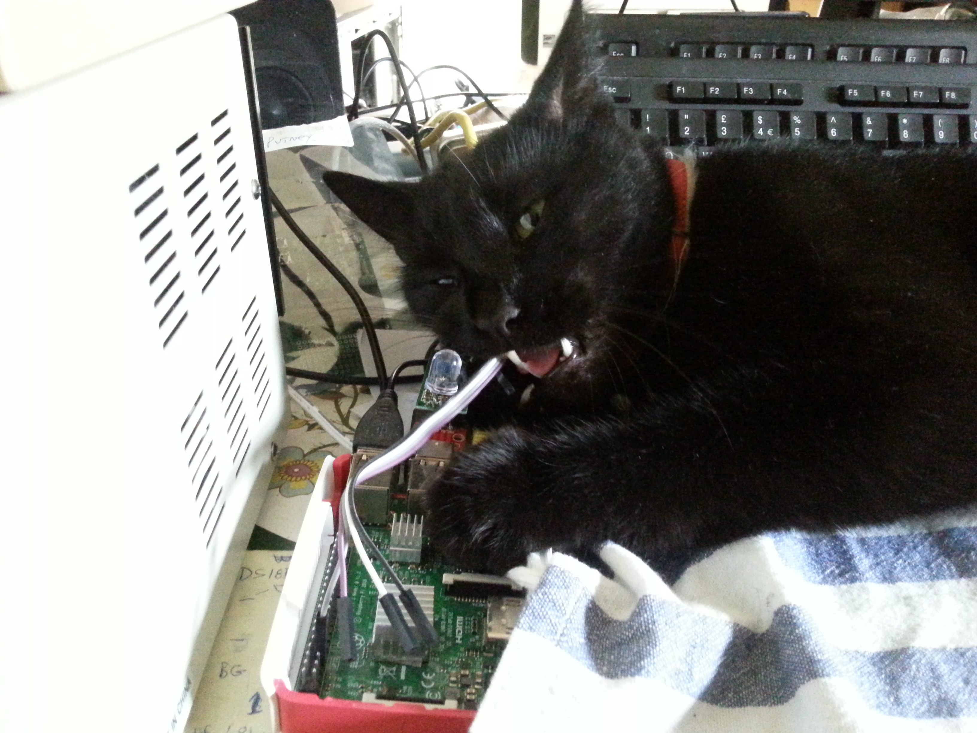
This is CAT5 chewing my wiring from the Cat Detector. The detector is powered by a 5v USB plug (red) and the RCWL is green. The 3.3 v Blue LED is directly wired to OUT and GND with no dropping resistor (current limited) and the output goes into the Raspberry Pi 3 GPIO. Notice only one wire attached as power and ground comes from the USB plug.

barewires commented 6 years ago

2017-11-10-222113_1366x768_scrot 
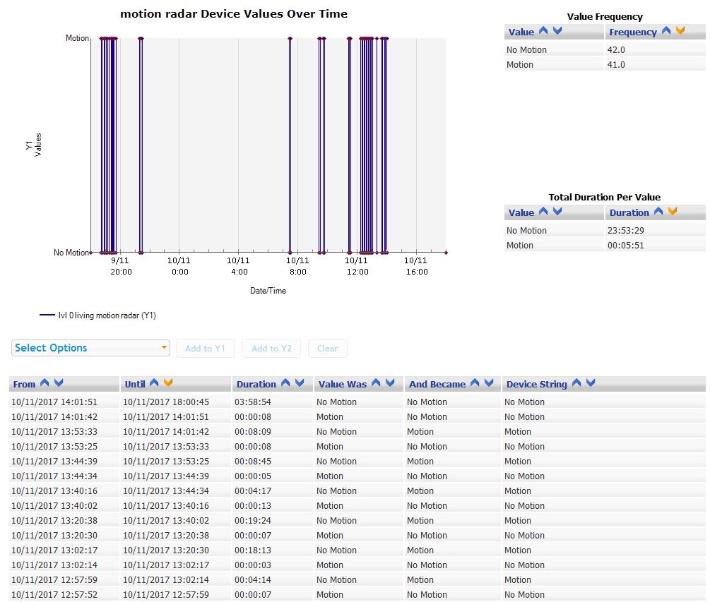
This is node-RED running in the whitebox. The Pi Zero W is headless so I remotely log in with 192.168.1.18:1880 from any tablet or desktop browser and edit the node-RED gui. Log files can be viewed by secure shell in any terminal, phone or tablet - ssh pi@192.168.1.18
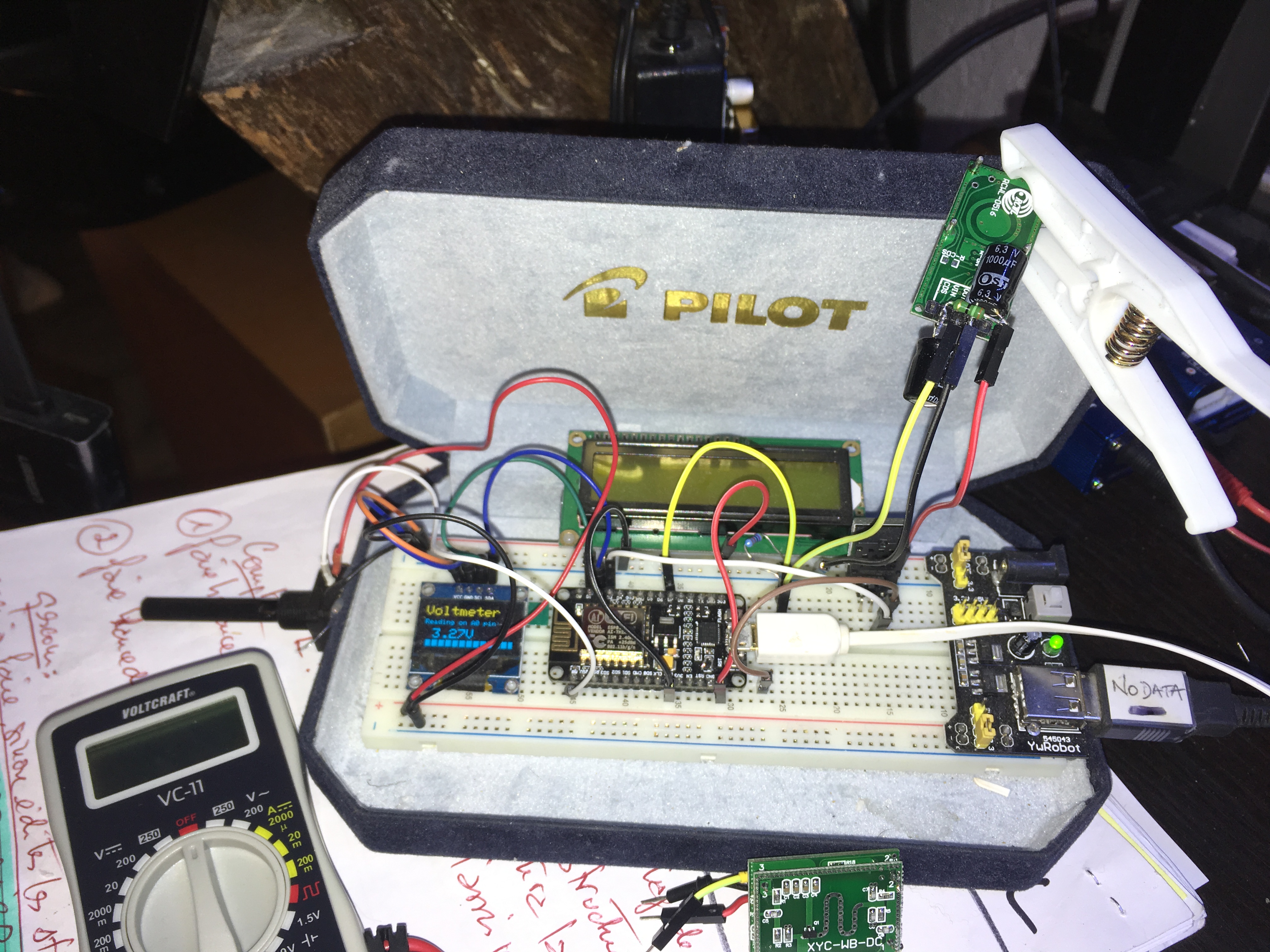
The date function is the most complex part of the system. This converts UNIX time in milliseconds to local time.

var date = new Date(msg.payload); msg.payload = new Date().toString(); return msg;

Any on/off activity is logged locally and emailed once only every 5 minutes. Twits are done the same way. Raw sensor activity produces so much data that it has to be filtered.

syedamerali commented 6 years ago

barewires thank you for your input. "Also the mass of metal on the big cap is so close to the circular capacitor trace, may be best to put it outside the active area, if at all" valid point - I will lay it down flat on the board that might be better. Actually I tried something else. With a view to making the RCWL directional I put some sticky non conductive tape on the back (circular side) of the board - then I put some aluminium foil on top of that. The detector output was constantly high. So much for that!! "I assume that the ESP is 3.3 volt compatible so I question the need for the logic level converter? It may be best to twist all power wires together, even though they are short." Right again. The RCWL needs 5V so you need to have a 5V supply. The 3.3V output from the RCWL board is not sufficient to run an ESP8266 so you would need to have a 3.3V supply for the ESP8266 also. I originally made this adaptor board board to interface with an arduino (5V) for its numerous AtoD inputs. This ESP adaptor board communicates with the arduino through the Rx Tx lines. I had this board lying around so I just used it. "Another thought is to power the whole thing with a mini or micro USB power supply and get rid of the cheap AC PS, remember you get what you pay for. :D". Excellent idea - never thought of it. All I need to do is find an easily usable female micro USB plug which mounts on the side of a plastic box with preferably a round hole.

ym58 commented 6 years ago

I put some sticky non conductive tape on the back (circular side) of the board - then I put some aluminium foil on top of that. The detector output was constantly high.

Do you mean that WITHOUT THIS FOIL the output was constantly high DESPITE your 10K pulldown resistor ?

syedamerali commented 6 years ago

The output was high with the foil in place. Once I removed the foil it started functioning normally. The pulldown resistor was in place when I put the foil on.

ym58 commented 6 years ago

Got you. I am a bit sick and tired to struggle with the RCWL board to make it work reliably ... have you ever tested the XYC-WB-DC board ?

syedamerali commented 6 years ago

My RCWL boards are now functioning reliably. I have just received a couple of HFS-DC06 boards which I will try out and let you know in a couple of days. No I have not tested the board you mention. regards

barewires commented 6 years ago

The only time I had false triggers / sluggish response was when the detector was both flat and perpendicular to a breadboard. Now I always put the sensor on a 3 pin Dupont extension of 5 cm and then I can move it to the optimum position.

syedamerali commented 6 years ago

These work beutifully - I have a couple of them outside the house. https://www.aliexpress.com/item/Body-Motion-Detector-Light-Switch-DC-12V-24V-360-Degree-Microwave-Radar-Sensor-HF-Detector-Light/32794241378.html?spm=2114.search0302.3.9.IRUk98&ws_ab_test=searchweb0_0,searchweb201602_0_10073_10152_10151_10536_10557_10537_10539_10055_10154_10550_10175_10552_10056_10155_10551_10059_10312_10554_10553_10314_10534_10313_10533_10577_10060_10084_100031_10083_10107_10307_10341_10065_10142_10340_10068_10343_10541_10342_10562_10345_10103_10102_10344-10552,searchweb201603_0,ppcSwitch_0&algo_pvid=dddc50a0-8f5b-41dc-adb4-e38726568990&algo_expid=dddc50a0-8f5b-41dc-adb4-e38726568990-1

ym58 commented 6 years ago

@syedamerali Beautiful design and quite handy to manage connections, although a bit expensive ... I think I'll give it a try. It is, in all respects, way better than my long enclosure (see my pic of yesterday) that cannot be operated any longer from an internal 2usd-chinese P/S, anyway ! What's the AWACS-like bump for ?

Have you also seen that one : https://fr.aliexpress.com/item/Hot-sale-9V-DC-24V-DC-360-degree-Microwave-Sensor-Light-Switch-Induction-Microwave-Motion-Sensor/32796897588.html It looks like it can be operated directly from AC/220V (although it's not quite clear from the AliBaba description if it is DC/9V-24V or AC/220V !)

ym58 commented 6 years ago

The only time I had false triggers / sluggish response was when the detector was both flat and perpendicular to a breadboard. Now I always put the sensor on a 3 pin Dupont extension of 5 cm and then I can move it to the optimum position

@barewires Yes, you must be right as I no longer have false triggers when sensor is under test at the end of Dupont wires and back to the breadboard ! Albeit I am still uncertain if this is due to the Dupont extension or to the rippleless "external" supply (provided here from my PC USB port) ... ! 2017-11-11 18 58 47

syedamerali commented 6 years ago

ym58 - this one works straight out of the box. The dome has a vertical antenna in its centre which is just a 0.5mm stiff wire soldered at right angle to the board. The problem with this detector is that it is all 220V. I had to isolate some tracks on the board and use the normally open contacts of the relay on the board to switch 12V DC. This 12V signal is fed to a z-wave binary detector running at 868.42 MHz. The 12V supply, the z-wave binary detector and the radar motion detector are housed in the same box - everything works flawlessly. Will try to post a picture of the setup later today.

ym58 commented 6 years ago

The problem with this detector is that it is all 220V.

Do you mean the one in your link or the one in my link ?

I had to isolate some tracks on the board and use the normally open contacts of the relay on the board to switch 12V DC.

Don't get it ...

syedamerali commented 6 years ago

my link. The photograps of my setup are attached. This detector is placed in a verandah and has a range of about 6m. radarzwave2 radarzwave1

syedamerali commented 6 years ago

Don't get it ... the radar detector operates a small relay which is housed in the white radar box and on the same PCB. I had to isolate the NO contacts from 220V by cutting some tracks so that I could use it for switching 12V which my binary sensor requires. This radar detector has small pots for (a) sensitivity (b) light level and (c) duration of trigger.

ym58 commented 6 years ago

Got it all now ! I am not familiar at all with z-wave. What are the pros and cons of z-wave versus wifi ? Is 6m the longer range one can expect from this technology ? Do you need a sort of in-house 868Mhz receiver/hub and how does it trigger an MQTT or email message ?

syedamerali commented 6 years ago

"What are the pros and cons of z-wave versus wifi ?" it is better explained here: https://community.smartthings.com/t/z-wave-vs-wifi/9078/2 please look at the comment by Labelle "is 6m the longer range one can expect from this technology ?" 12m is claimed by some. My experience is to the contrary. For zwave you need a hub which may be a USB stick (I use a z-net controller from homeseer). The computer in which the USB is plugged has software which talks to all the devices through this hub. Software can be free - Domoticz, smartthings or expensive Homeseer (which is what I use). This software is generally capable of multiple technologies including z-wave, zigbee, X10, insteon, wifi etc. The software allows you to develop "scenes" if this happens do this, these scenes may be activated in a number of ways, motion temperature, humidity, cameras or the switching on or off of other devices - the permutations are endless. I would suggest you go to this site: https://www.fibaro.com/en/products/motion-sensor/ and look at the video for motion sensor - it will blow your mind. Look under products to see what is available. look under sensors, actors, gateways etc. each sensor / actor is about 50 GBP each. I have over fifty in my house.

ym58 commented 6 years ago

@syedamerali I have read it all (and possibly understood ;-) ... z-wave is quite impressive ! Fibaro looks like an elegant, no headache, low-power solution targeting the streamline home automation consumers. However, it doesn't give DIY's guys like us a "sense of feeling" ... I guess that tinkering cheap ESP8266's stuff is rewarding. But should I be able to find also cheap bare z-wave sensors and easily programmable z-wave hubs, I would definitely fancy giving it a try for the battery-powered capability is very enticing.

syedamerali commented 6 years ago

Actually there is a much better write up on z-wave on wikipedia. "Sense of feeling". Each sensor / actor can have upto 200 customisation parameters. You cannot imagine that a simple switch which we use our finger to operate can have so many configurable parameters. Look at the advanced parameters in the attachment. So it definetly gives you a sense of feeling and is most rewarding and you can do so much more. There are no cheap z-wave sensors. I have tried chinese ones (NEO coolcam) total waste of time. Actually, it is not a good idea to have a lot of battery powered devices in your z-wave mesh network. Unlike the powered ones they do not act as repeaters. This weakens the mesh network. Apart from the mesh network the good thing about z-wave devices is:

  1. They are physically so small that you can stick them into existing switch boxes. And in addittion to be operated remotely they can also be operated by the existing manual switches.
  2. Once a command is given to an actor to do something it acknowledges that it has done it. It is only after this acknowledgement that the status changes in your software for that particular actor.

If you are thinking of diving into z-wave, try and stick to z-wave+ certified devices. They are faster, have more range and many more customisable features.

binarySwitchFGS-2x3-EN-T-v1.2.pdf

ym58 commented 6 years ago

@syedamerali I am technically completely convinced ... by your arguments as well as by my readings ! A z-wave+ mesh with a raZpberry hub is definitely something a "native tinker" would like to set up ! If it weren't for the costs of accessing the z-wave+ technology .... :-( There's quite a difference between a fellow like you owning 50+ z-wave devices for home automation "valid" reasons and a guy like me who just tinkers ... for the beauty of it !

By the way, is this something you salvaged from a Fibaro enclosure ? tmp

syedamerali commented 6 years ago

It is this: https://www.fibaro.com/en/products/universal-binary-sensor/