Increasing C10 too much fries the MOSFET.
C10 must be small enough that it will turn off the MOSFET before the MOSFET falls out of the safe operating area and be big enough to fully charge the capacitors. What's an appropriate value?
I used another QLA (v1.2) because I fried the original one.
QLA without modification (C10 = 0.01 uF)
No load connected.

CH1 48V input. CH2 V-MOTOR. CH3 C10.
QLA with C10 = 0.11 uF
No load connected.

CH1 48V input. CH2 V-MOTOR. CH3 C10.
Rise time estimation
Using QLA with C10 = 0.11 uF. No load connected.


The total rise time is about 3 ms. Should be much shorter if the capacitors don't discharge between rises.
Current estimation with no load
I measured the slope of V-MOTOR to estimate the current.
Using QLA with C10 = 0.11 uF. No load connected.
Charging current

The slope is very consistent (about 17 - 18 kV/s) throughout the entire 0-48V range.
I = v_dot * C
I_charge = 17.3 kV/s * 1200 uF = 20.8 A
This is 30% higher than the set current limit.
Discharging current

I_discharge = (-4.6 V / 39.1 ms) * 1200 uF = -0.141 ACurrent estimation with dSIB+3SUJ attached
The behavior is not consistent. I observed three types of behavior:
- A more-struggle version of the no-load behavior.
V-MOTORtakes more tries to rise to 48V.

- Distorted version of 1. See two figures below.


- Rises to 48V without hiccuping. See two figures below.


Notice that the C10 did not get charged when current is at 19 A. Maybe I made a cold solder joint? but it charged slower than other measurements.
During the test, I observed 1 and 2 first. Then I started to notice that when enable, the indicator lights for the amp axes that have SUJ plugged fast blink a couple times then turn off (indicating fault). The amp status light on the axis without SUJ stayed on.
After a couple on/off cycles, the behavior switched to 3 and stayed that way. Power cycling did not change the behavior.
Unplugging the QLA from dSIB changed the behavior back to 1.
Charging - not much difference.

Discharging - 0.179 A. About 40 mA higher than no load.

Simulation
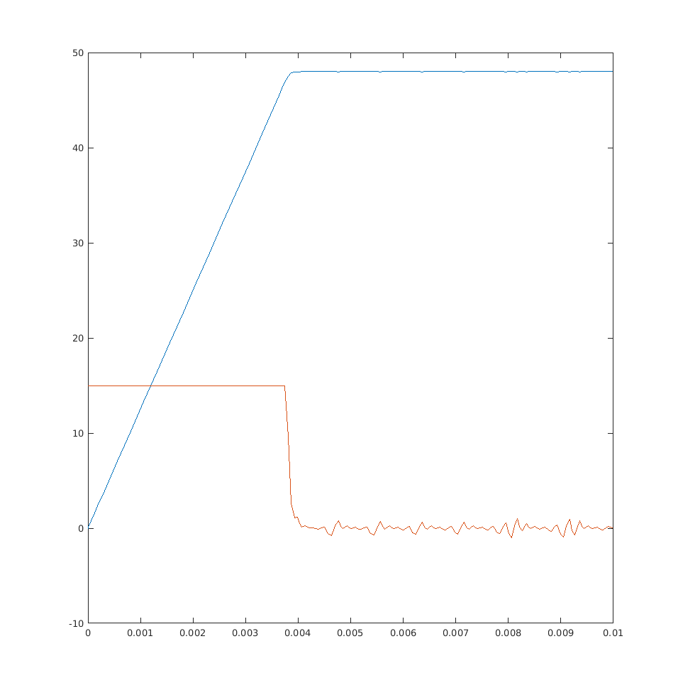
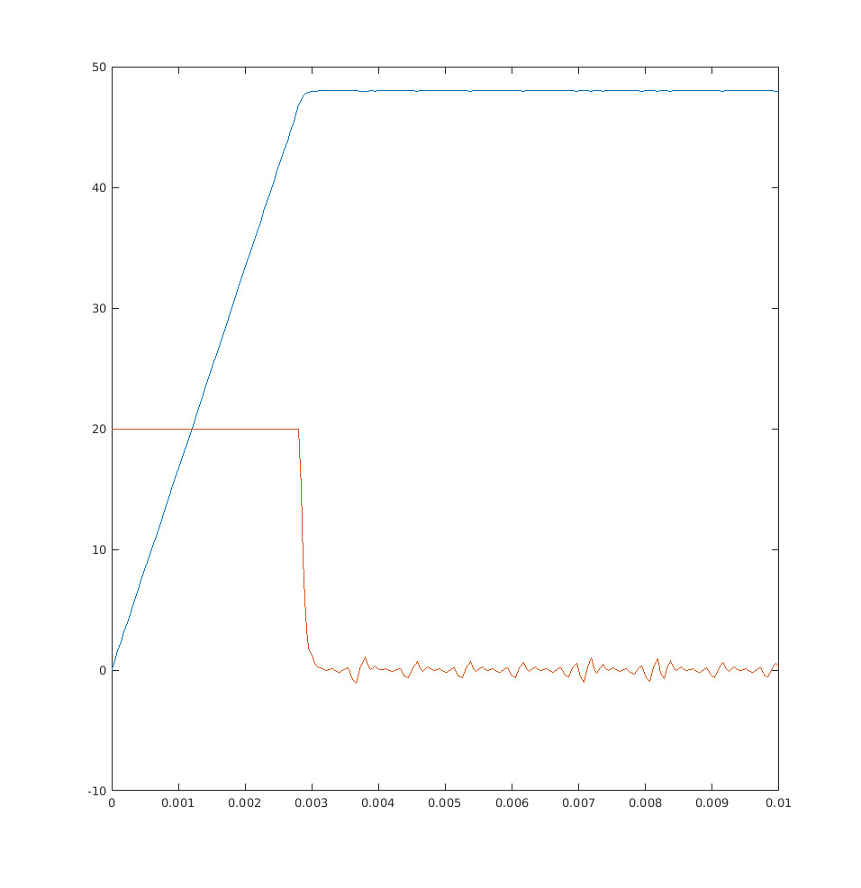
To better estimate the rise time, I modeled the system as following.

Which translates to this matlab ode function.
I assume the system ESR is 50 milliohms (power supply, connectors, resistors, mosfets).
Red is the current flowing through the MOSFET in Amps. Blue is V-MOTOR in Volts. X axis is time in seconds.
Current limit at 15A
v_in = 48;
i_lim = 15;
r_esr = 0.05;
c_out = 1200e-6;
r_leak = inf;
about 4 ms rise time.
Current limit at 20A
v_in = 48;
i_lim = 20;
r_esr = 0.05;
c_out = 1200e-6;
r_leak = inf;
about 3 ms rise time.. closer to what we see in real measurement.
Effect of leakage
v_in = 48;
i_lim = 15;
r_esr = 0.05;
c_out = 1200e-6;
r_leak = 10;
Even with a 10 Ohm resistor draining the V-MOTOR, the rise time is still under 5 ms.


 (Enable QLA power after the power supply is fully on.
  (Turn on the power supply the same time as the QLA motor power. Rise time ~25 ms.)
 (Plug in the power supply after enabling the QLA motor power. )
 (CH1:
(CH1:  (broken)
 (working)
Symptom
Some QLA fails to enable power with 48V power supply and dVRK Setup Joints (QLA+dSIB+SUJ). When the FPGA turns on
PWR-EN,V-MOTORonly rises to about 3V.Q14surge protection MOSFET gets hot.Conditions
The symptom seems to be related to the number of SUJ plugged into the dSIB. Plugging in any one of the SUJ does not cause the problem except for PSM1. Plugging two or more SUJ always cause the problem,
Loading the
V-MOTORafter the protection MOSFET with a 20 ohm power resistor to GND always reproduce the issue without dSIB/SUJ.I could not reproduce the problem with an adjustable power supply with 2A current limit. The input voltage dips at powerup. After the dip, the output voltage rises normally. The problem only exists when the QLA is powered by a high-current (>10A) 48V power supply.
"Normal" powerup behavior
I captured the waveforms below from a QLA powered by a high-current 48V power supply at power enable. No load is attached to the QLA.
CH1
V-MOTOR. CH2 48V input. CH3Q14MOSFET gate. CH4U28SNScurrent sense (AC coupled).When
U28gets power enable signal, it turns onQ14and starts to charge the amp input capacitors. The inrush current triggers the current regulation, then after the time set byC10elapsed, triggers the shutdown. After a cooldown period set byC10, it turns back on the MOSFET and continues the loop until the capacitors are charged.Not included in the screenshot is the
/MV-FLTsignal. During ramping up,U28spends most of its time keeping the MOSFET off while waiting for the fault timer to reset.Broken behavior
The following waveforms were captured with QLA connected to dSIB and two SUJ.
CH1
V-MOTOR. CH2 48V input. CH3Q14MOSFET gate. CH4U28SNScurrent sense (AC coupled).When the capacitors drain faster than they charge, they never get fully charged.
U28loops between charging the capacitors and waiting for fault timer to reset.SolutionThe problem is caused by
Q14MOSFET turning off too early and waiting too long before turning back on. IncreasingC10increases the time between starting the current regulation and turning off the MOSFET, but also increases the cooldown time between turing off the MOSFET and turning it back on. If load capacitors do not get fully charged before the MOSFET turning off, there is risk of the capacitor discharging more than it charged during cooldown. To guarantee normal powerup behavior,C10must be sufficiently large to allow linear operation of the MOSFET for as long as the rise time ofV-MOTORat the maximum allowed current, but not exceed the heat dissipation capacity of the MOSFET.Replacing C10 (0.01uF) with 2.2uF seems to solve the problem.The value is roughly estimated based on the timing diagram in the LT4356 datasheet. Capacitor ESR and MOSFET thermal properties must be considered to obtain a final value for the replacement.With the replaced capacitor, the previously-not-working-with-SUJ QLA functions normally with dSIB+4SUJ.
The following waveforms were captured with the fixed QLA connected to dSIB and two SUJ.
CH1
V-MOTORThe motor voltage rises smoothly without causing the MOSFET to shutdown. The MOSFET does not seem to overheat for the duration of linear operation.
The cause of dSIB+SUJ draining
V-MOTORis still under investigation.