 DaneEvans
commented
3 years ago
DaneEvans
commented
3 years ago There should be no need to update the schematic, and it will only give more places for things to go wrong.
Just create a new footprint, allocate it to the schematic parts and update the PCB.
I'm happy to do a review and approve it, but as I'm not going to update mine, I'm not going to do the change myself, if the pinout matches it shouldn't be too much work to route though.
On Wed, 3 Mar 2021, 4:35 pm tiadobatima, notifications@github.com wrote:
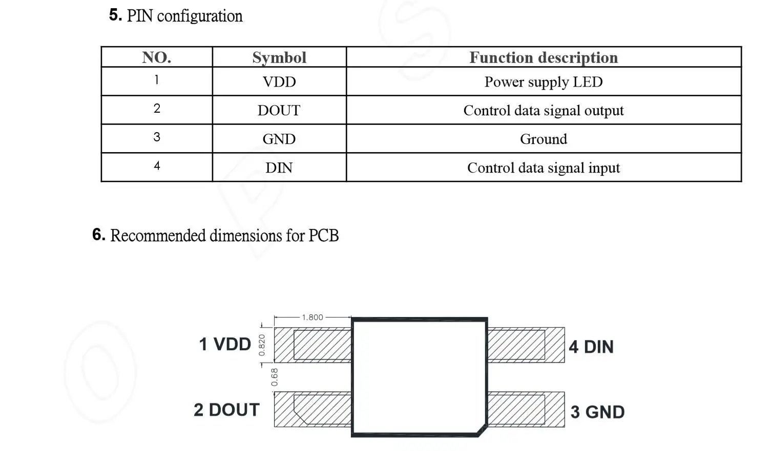
Hello there... Not sure this is wanted, but I'm starting the work to update the SofleRGB to use SK6812-MINI-E which seems to be considerably easier to solder vs the regular SK6812-MINI.
I have updated the schematics to use the MINI-E. I'm not good with Kicad, so I'll need some more time to update the footprint, but I think this is ready for early review if you're interested.
I couldn't find an official datasheet only but this is what some vendors on Aliexpress are publishing: https://ae01.alicdn.com/kf/H79d59ee537124777a478665921acaa59A.jpg
I have the work on this branch on my fork: https://github.com/tiadobatima/SofleKeyboard/tree/sk6812-mini-e
And to make your review a bit easier, I created a PR against my fork's master: tiadobatima#1 https://github.com/tiadobatima/SofleKeyboard/pull/1
Thanks! :)
— You are receiving this because you are subscribed to this thread. Reply to this email directly, view it on GitHub https://github.com/josefadamcik/SofleKeyboard/issues/45, or unsubscribe https://github.com/notifications/unsubscribe-auth/AFIRN4LMB6NPJZP6QX5QZ7DTBXDDPANCNFSM4YQRR7NQ .
 tiadobatima
 josefadamcik

 joecabezas
 DLopezGo90
 brianlow
 utlandr
 page200
 trougnouf
 pfn
pfn dmikhalsky
 KlausHans
 taydevr
Hello there... Not sure this is wanted, but I'm starting the work to update the SofleRGB to use
SK6812-MINI-Ewhich seems to be considerably easier to solder vs the regularSK6812-MINI.I have updated the schematics to use the
MINI-E. I'm not good with Kicad, so I'll need some more time to update the footprint, but I think this is ready for early review if you're interested.I couldn't find an official datasheet only but this is what some vendors on Aliexpress are publishing: https://ae01.alicdn.com/kf/H79d59ee537124777a478665921acaa59A.jpg
I have the work on this branch on my fork: https://github.com/tiadobatima/SofleKeyboard/tree/sk6812-mini-e
And to make your review a bit easier, I created a PR against my fork's master: https://github.com/tiadobatima/SofleKeyboard/pull/1
Thanks! :)