jpcima / rc-effect-playground

mystery audio effect (WIP)
Other
3 stars 2 forks source link

Comparing to Roland synths #2

Open jpcima opened 4 years ago

jpcima commented 4 years ago

@SpotlightKid: If you want some refernce recordings, let me know.

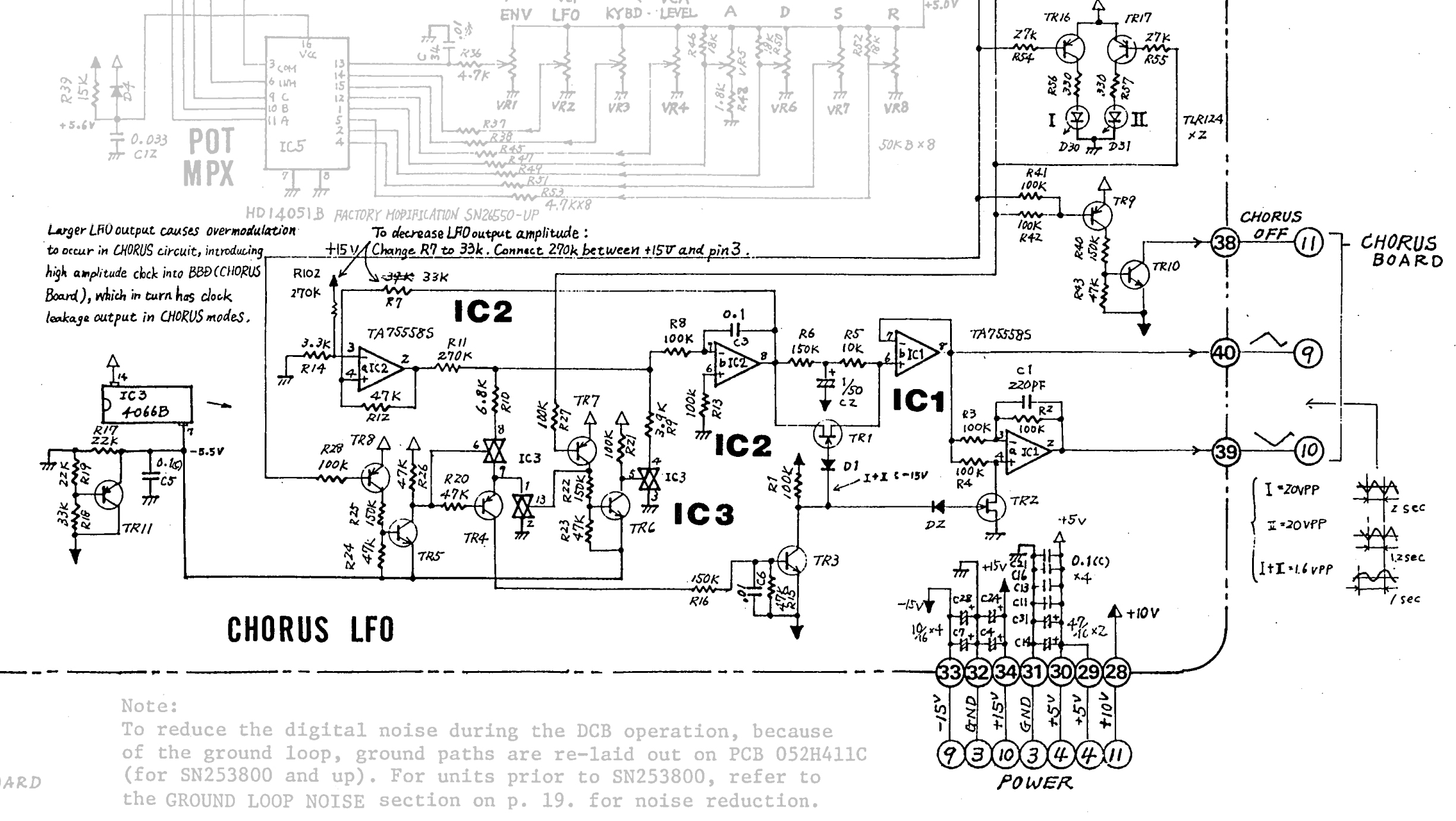
Yes please, it would give me a idea of what we're targeting. A pair of recordings with chorus on and off, using the simplest input signal and the most dry configuration possible.

It wouldn't be bad also to measure for 1 low note, 1 mid and 1 high.

Is it possible to derive the delay time and modulation depth from the schematics?

By the knowledge of the chip and circuit, I would guess nominal delay approximately of 20ms.

It's difficult to know from schematics directly, although datasheets are able to help somewhat. Simulation is also complicated, as there don't exist SPICE models that I know of MN3101/MN3009 chips.

A decent possibility if you're able, it's to capture electronic signals directly on device.

But I think overall, the best way to go is based on current the gray-box method; ie. take recordings of the target chorus, and then adapt implementation as needed.

jpcima commented 4 years ago

I've found this demonstration sound: https://www.youtube.com/watch?v=HM-fIEEwaaA Around 00:25, there is a simple bass sawtooth, and from analyzing the sound region in audacity, it can be observed quite easily what is the variation range of delay.

Another thing, from collected information on the topic: the Juno chorus did not use the analog delay circuit with a compander for noise reduction. It's only the Dimension D which used a compander. Regardless, I guess it will be a good idea to implement it.

SpotlightKid commented 4 years ago

Hey, good find.

jpcima commented 4 years ago

It's a wave of this shape. From it, it can be seen the original, and then the two delays coming after. Capture du 2019-10-11 13-33-30

The next thing is: I'll load this in numpy, and try estimate these delays with minima and maxima finding. Then, the variation of delay can be extracted in a plot, and this will be easier to reproduce it.

jpcima commented 4 years ago

A program is available in tools which produces data files of delays for gnuplot. But it's not accurate at all, and output is not so useful until fixing it.

It outputs tuples of (absolute time, left channel delay, right channel delay), with units in seconds.

jpcima commented 4 years ago

As imprecise as it is, this data still shows a visible tendency. If I make some gross extrapolations from these calculations, I can have some approximate characteristics.

Juno 60 (I): delay 1.5ms to 3.5ms, triangle 0.95 Hz Capture du 2019-10-11 15-31-19

Juno 60 (II): delay 1.5ms to 3.5ms, triangle 1.6 Hz Capture du 2019-10-11 15-29-45

SpotlightKid commented 4 years ago

The schematic says 0.5 Hz (Type I) and ~0.83 Hz (Type II), though.

jpcima commented 4 years ago

Well yeah, considering this LFO is input to a BBD clock generator, and BBD clock is proportional to inverse delay by a factor 2, that likely confirms it; because these frequencies which you cite are also proportional to measurement by a factor 2.

jpcima commented 4 years ago

Progress: this is a faust module emulating a delay with the lfo characteristics. (no bbd) You can see it compared to the juno60 sample in the video recording. chorus.dsp.gz chorus.ogv.gz

jpcima commented 4 years ago

Note: other resource of interest here https://github.com/pendragon-andyh/Juno60/tree/master/Chorus

jpcima commented 4 years ago

The sample files of youtube origin don't seem correct as a reference, they appear like mixed-down, and it's suspicious that they have two delay images, it should have 1 only.

I took the samples from the comment above's link, and did it over again. Try with the new file, which is expected to be nearly correct chorus2.dsp.gz

jpcima commented 4 years ago

I've pushed the chorus3.dsp prototype. This one adds I+II mode. It's a rewrite, it's simplified and fully functional, and it's matched with sawtooth sound samples found at the repository: https://github.com/pendragon-andyh/Juno60/tree/master/Chorus

I think the I+II frequency rating in that document's table is not matching, I had to reduce it to a lower value.

I think we can possibly go with this one, I'll like to hear your feedback about it.

jpcima commented 4 years ago

Next analysis, this is modulation of the I+II case.

It approximates to a sine of frequency 9.75Hz, delay variation 3.22ms to 3.56ms. Approximated in green on the below plot.

Capture du 2019-10-12 18-29-58

jpcima commented 4 years ago

I've rewritten the plugin with faust and the BBD delay hacked inside. The code is pushed on the master branch.

jpcima commented 4 years ago

Hi @b3ll, we are researching Juno chorus on a request of @SpotlightKid, and collect some information and research on this topic; so feel free to hop in if you like.

are you owner of Juno 106 by any chance?

jpcima commented 4 years ago

By experiment on sample juno60-1, I find following data lfoRate = 0.513 (no change) delaymin = 1.54e-3 (was 1.66e-3) delaymax = 5.15e-3 (was 5.35e-3)

Also the triangle wave is found asymmetric, by duty 49.3333%. (it rises faster than it declines)

jpcima commented 4 years ago

Jx-3p chorus: same as Juno 60 except lfoRate = 0.48 triangle duty = 46 %

jpcima commented 4 years ago

The JX-03 is particular, it used this curious sine-triangle hybrid waveform.

delaymin=1.43e-3 delaymax=4.33e-3 lfoRate=0.462

Note: as such, one must be careful about getting the inverse LFO by doing (1-x) of the original, as it will not work for this case.

jx03

channel1.dat.gz channel2.dat.gz

Faust code of JX-03 "sine-triangle" LFO

lf_sinetri(freq) = rdtable(tablesize, sinetriwaveform(tablesize), int(os.phasor(tablesize, freq))) with {
  tablesize = 1 << 16;
};

sinetriwaveform(tablesize) = ba.if(p<0.5, s(p), 0.5*(s(p)+t(2.*(p-0.5)))) with {
  p = float(ba.time)/float(tablesize);
  s(p) = sin(2*ma.PI*p);
  t(p) = ba.if(p<0.5, -2.*p, 2.*p-2.);
};
b3ll commented 4 years ago

@jpcima wow! this all sounds super cool. I don't own a 106, but I do own a System 8 which emulates a 106 (using hardware modeling), however I won't be home for another 2 weeks to test it :/

jpcima commented 4 years ago

I find the mixing part of direct signal vs chorus signal from schematic. It has an identical summing opamp part on all of Juno60/106/JX3P.

It's the following gains: g1=(-Rf/R1) and g2=(-Rf/R2) where Rf=100k R1=47k R2=39k

It establishes that direct signal is mixed in at -1.62dB compared to processed signal, which makes the delay a slight bit prominent over original. I have modified chorus.dsp source for this gain relation.

@b3ll it's a nice beast ! well feel free to contribute to our sample set anytime :)

b3ll commented 4 years ago

I should be able to in a week or so!