 kcuzner
commented
6 years ago
kcuzner
commented
6 years ago Firmware Perspective
At first glance, I see no reason this couldn't be used on an ATTiny10 since it has the required peripherals and space:
- 1024 bytes flash
- Pin rising edge interrupt
- A timer
However, it should be noted that the ATTiny10 has a 16-bit counter, while the ATTiny13A only had 8 bits. You will need to recompute the constants ONEWIRE_RESET_TICKS and ONEWIRE_READ_TICKS. You may also end up having to either adjust the prescaler or use a initial value in the timer to prevent overflow from taking too long.
Hardware perspective
Let's look at the schematic. I'm going to assume you've read up on the 1-wire protocol and how it is usually driven. The 1-wire signal will be applied to P1 (ground to pin 2, signal to pin 1).
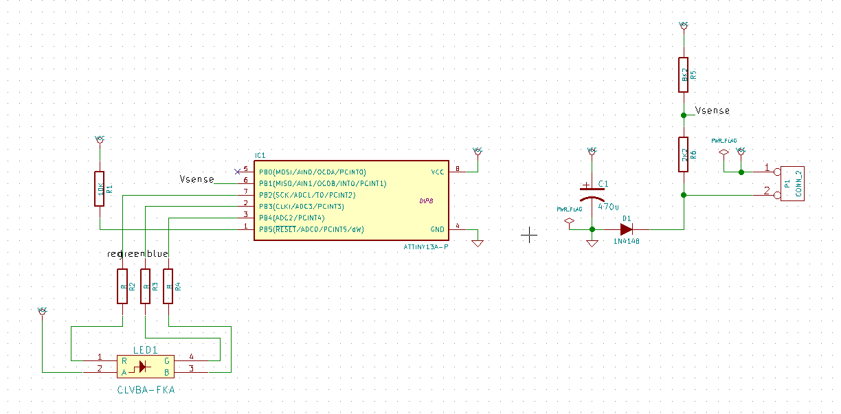
The input connector P1 has its pins in one of two states:
- The voltage on pin 1 is greater than pin 2. In this state, the diode is forward biased (note that GND is 0.7V relative to pin 2). The capacitor now charges. The main issue here will be with your driver. Generally 1-wire uses a pullup of somewhere beween 5K and 1K. At its worst case, your LED will try to draw 60mA from that 1K pullup, which will basically drive the voltage across P1 to zero, or at least to the point where the diode is nearly turned off (assuming it has already discharged the capacitor, though it might never even charge). You will need to use a fairly strong, push-pull driver for your 1-wire circuit. I think something like a standard gate driver used as a buffer could fit your needs (look at the MCP1402 for an example). You might also be ok with just a P-channel mosfet as I suggest in the readme. Important note: This only works because the microcontroller never responds back to whatever is driving P1. You can't have the microcontroller respond and have this super-strong driver. Because of the resistor divider R5/R6 you won't blow anything up, but the driving source is so strong you can never hope to pull it down to send a message back to the master. You'll have to get a bit more creative if you need bi-directional communication (maybe only using the driver during idle times and using a pull-up+open-drain setup for the rest of the times, etc).
- The voltage on pin 1 is equal to pin 2. This is the zero state, no charging is occurring. The issue here will be with the size of the capacitor. You will need to make sure it is big enough to sustain the 60mA drive current long enough so that the microcontroller doesn't shut off. I think 470uF is more than big enough for the 500uS that it takes for the one-wire bus to reset, assuming you charge the capacitor very quickly afterwards with your driver.
Now, there is one other issue: Brown-out. This device is designed to brown-out since it runs off a capacitor that is slowly discharging. I could not find any mention of a brown-out detect circuit on the ATTiny10, so you may need to provide your own (please read this application note by Atmel about building an external brownout detection circuit). If you do not provide some way to reset the device when the power dips too low, you will get undefined behavior and the microcontroller will misbehave. The device may not respond to onewire commands or may do something really strange.
 MaurinElectroTextile
Do you think that your code can fit in the ATTiny10? http://www.atmel.com/images/atmel-8127-avr-8-bit-microcontroller-attiny4-attiny5-attiny9-attiny10_datasheet.pdf I'm interested to use it to drive a 60 mA LED. Merci ;-)