keirf / flashfloppy-osd

On Screen Display and keyboard controller for FlashFloppy
The Unlicense
57 stars 15 forks source link

Implement video input switching capability using Amiga hotkeys and master-slave communication between two FF_OSD enabled blue pills #44

Open tkurbad opened 2 years ago

tkurbad commented 2 years ago

Hi,

this will be a longer one, but bear with me!

I own one of those AA3000+ Amiga mainboards sold by user 'hese' on Amibay. I'm putting it into a Amiga 3000 case as it is supposed to.

While I want to equip the final setup with a FlashFloppy driven Gotek, I want to retain the original Amiga 3000 look. In particular, I don't want to alter the case in any way. So, FF_OSD controlled by the Amiga keyboard is the way to go.

The AA3000+ board has a built-in video switch that is able to switch the VGA output between two video sources. Usually one of those is the Amiga's AGA output and the other some kind of RTG card, in my case a 3DFX Voodoo3 PCI card.

I want to use the FF_OSD hotkeys to (a) switch between four Kickstarts as in the example in default_config.c by means of U0 and U1 and (b) to be able to manually advance the 3-position video switch to either "automatically" (1) switch between the two video sources or choose Amiga or RTG output manually. This should be accomplished by user pin U2 on the FF_OSD.

Also, I want the OSD to appear in both, the Amiga and the RTG output.

_(1) Automatic switching is accomplished by a piece of software called switchcontrol. It monitors the state of the graphics driver and drives the serial port's CTS signal low as soon as RTG output is desired. For automatic switching to work, CTS has to be jumpered to the input signal of the video switch circuit. If the jumper is removed and the switch input is left floating (or driven high), the output is fixed to the Amiga signal, if switch input is driven low, the output is fixed to RTG. On the mainboard, there's a pin header that has CTS - SWITCH_INPUT - SWITCH_INPUT - GND Thus by connecting a on-off-on switch, you could switch between auto, Amiga, and RTG. One goal is to accomplish the same by a simple state machine driven by U2._

In an initial working setup, I use two Blue Pills, connected in parallel to the Gotek's I²C port. One, the "master" plugs into the Amiga input of the mainboard and connects to the keyboard. It also has U0 and U1 switching by hotkey enabled as in the ROM switching example and U2 as a momentary button driven high by F10 on the keyboard. This Blue Pill has A0-A1 jumpered.

The second, let's call it "slave", Blue Pill connects to the RTG input on the mainboard and does not have A0-A1 jumpered. This way, the "master" receives all the Amiga keyboard commands and is able to control the Gotek, while the "slave" only receives the Gotek's output.

In my final working breadboard draft, U2 of the "master" egde triggers an interrupt of a PIC12F629 (which I happened to have laying around from another project). The PIC has an output connected to SWITCH_IN and a second input connected to the CTS output of the Amiga. Each detected low-to-high-edge of U2 advances the following state machine:

1 (Initial): Mirror CTS on SWITCH_IN (=automatic mode)
2: Switch output to input mode to simulate an open drain in high impedance (=Amiga)
3: Pull output low (=RTG mode)
-> back to 1

To illustrate, here's my test setup (without the PIC12F629) Test_Setup

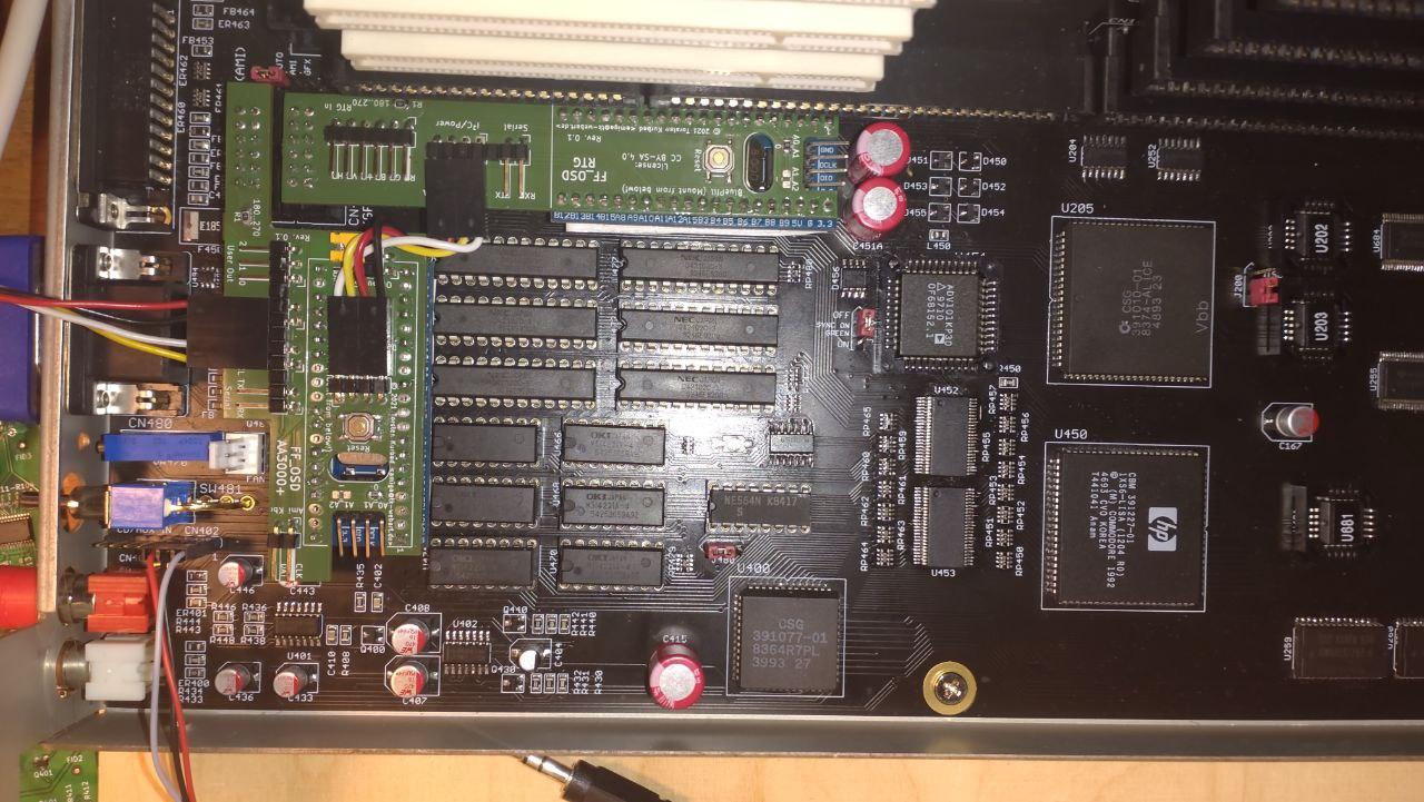
Rev. 0.2 of the "master board" integrates the PIC circuitry (and also has the cutout for the Blue Pill's oscillator corrected :-) FF_OSD-AA3000+_Rev_0 2

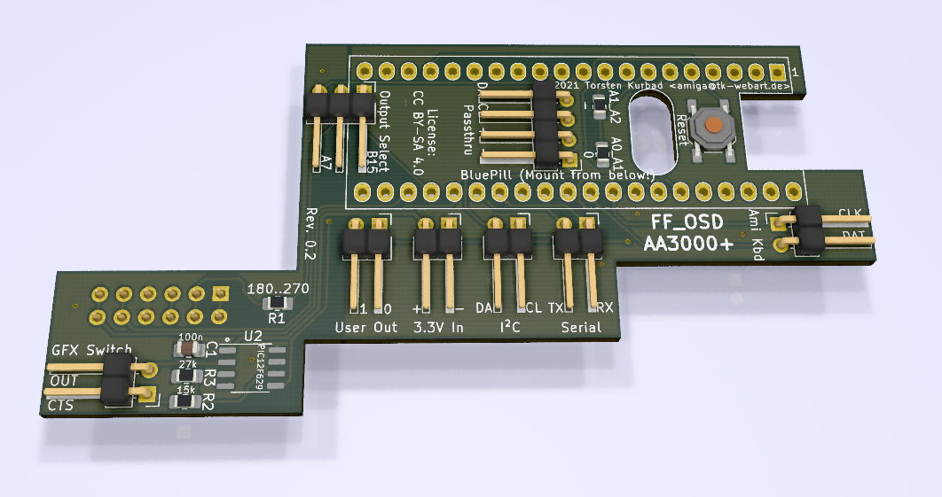
And here's a rendering of the much simpler "slave board" FF_OSD-RTG_Rev_0 2

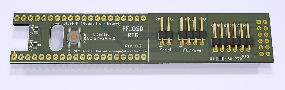
While this setup works well enough, it has some drawbacks: (1) It uses two Blue Pills where only one might be necessary, given H- and V-Sync can be provided twice independent from one another, and SPI1 and SPI2 can be used as outputs simultaneously, one for RTG the other for Amiga GFX. (2) The PIC is very much of an overhead, because one additional input on the Blue Pill for CTS would suffice to implement the state machine therein. I just didn't like the idea of choosing one arbitrarily and starting to maintain my own fork of FF_OSD with this additional state machine. ;-) (3) The "slave" Blue Pill doesn't know anything about the Amiga keyboard. Thus, all the output associated with hotkeys is only visible while Amiga graphics input is chosen. In addition, only the "master" has the nice multi-line output that is triggered by jumpering A0 and A1.

So, the logical idea would be to consolidate all of this into a single Blue (or, if Blue is not powerful enough) Black Pill.

On a side note, this setup would be interesting for people using the so-called "Ratte-Switches" for switching between Amiga and RTG output and perhaps for other scenarios where you don't need the switching but have two different video outputs on the same machine.

Much of this behaviour could be made accessible through the configuration menu I guess (well, a man can dream... ;-)

@keirf What do you think about this proposal? Does it have the slightest chance of being possible to implement?

keirf commented 2 years ago

I don't think it would be easy to drive two OSD outputs simultaneously, but switching between VGA and AGA modes on PA7 and PB15 respectively is more plausible. Do you need H/V syncs for both? Would need care picking the second HSYNC pin. Perhaps PA9 as this is a spare channel on Timer1 (existing PA8 pin uses T1Ch1, so using T1Ch2 would be not too hard to implement). Unfortunately this collides with the serial pins (useful for debug) but serial could perhaps be done on UART2 on pins PA2 and PA3.

In summary:

  1. Two built-in flash configurations. One for VGA, one for AGA.
  2. Hotkey to switch between the configurations.
  3. A bit of pin remapping for VGA so that independent Sync pin inputs are used, eg. H=PA9, V=PA11.

A further complication on (2) is that full mode switch usually requires a reset of the Blue Pill. Just because that's easier to implement and mode switches would usually be rare. So might need to fix that, or remember some state across reset.

tkurbad commented 2 years ago

Do you need H/V syncs for both? Would need care picking the second HSYNC pin.

I guess so, yes. Both, AGA and RTG cards usually need H- and V-Sync. One can switch jumper the AGA output to do sync-on-green, but my guess is that this would further complicate things instead of helping...

Perhaps PA9 as this is a spare channel on Timer1 (existing PA8 pin uses T1Ch1, so using T1Ch2 would be not too hard to implement). Unfortunately this collides with the serial pins (useful for debug) but serial could perhaps be done on UART2 on pins PA2 and PA3. Yes, that sounds plausible, while keeping in mind that UART2 is 3.3V only and people need to be warned not to connect 5V USB-UART adapters to it.

In summary:

  1. Two built-in flash configurations. One for VGA, one for AGA.
  2. Hotkey to switch between the configurations.
  3. A bit of pin remapping for VGA so that independent Sync pin inputs are used, eg. H=PA9, V=PA11.

A further complication on (2) is that full mode switch usually requires a reset of the Blue Pill. Just because that's easier to implement and mode switches would usually be rare. So might need to fix that, or remember some state across reset.

Thinking aloud:

What if we keep the concept of using two separate blue pills, but implement some kind of communication between them. The idea would be to have a kind of master-slave setup, where the slave isn't even connected to the Gotek via I²C. Instead master and slave communicate via their UART interfaces with the master sending the slave the text to display on the OSD.

This would just be one additional config option (which defaults to master).

To not interfere with debugging/config, a kind of handshake upon cold reset could be initiated. I.e., after booting up, the master would send some "magical" sequence saying "I am master" in regular intervals while not in config mode. Once a slave sees that sequence on its RX, it responds with another sequence letting the master know that it is ready to receive text from now on.

Everything the slave receives on UART is henceforth displayed on its OSD...

tkurbad commented 2 years ago

Thinking further, for this setup, even a config option might be overkill. A device could be set into slave mode by putting a jumper across SCL-SDA (or somewhere else, if that wouldn't work).

keirf commented 2 years ago

This is possible. It might be easier to use I2C2 on the master and communicate using I2C. This gives you some framing, for example. The slave wouldn't be easily configurable but I suppose you would set him up in master mode, and thenceforth he wouldn't need configuring. Configuration things like OSD box position wouldn't affect the slave unless I2C commands to do so were added...

tkurbad commented 2 years ago

Yes, I2C has the additional benefit of being a open drain bus by default, so - in theory - you could drive more than one slave from a single master. Can't think of a scenario where this would make sense, but you never know. ;-)

Anyway, for my current design, this would simply mean to routing I2C2 instead of I2C1 to the passthrough connector on the master PCB, which is easily accomplished.

What do you think about part 2 of my initial question - having that switching sequence of "mirror an input" - "high (impedance)" - "low". I can't think of a nice way to generalize this "state machine" approach other than having some kind of callback function attached to the hotkeys. Also, it would be nice to have an input pin we can agree on for such mirroring purposes. Ideally, this pin would be from the group of the five volt tolerant ones.

tkurbad commented 2 years ago

Oh, and I like the idea of being able to configure the slave through the master by I2C. :-) Of course, the general/initial parameters can be set up in advance, but being able to set the slave's OSD position via the master would be very nice.

keirf commented 2 years ago

Regarding the hotkey switch sequence, I'd probably hardcode it and give it a new name/id. Not troubled for Flash space so all sorts of things can be shoved in, really.

Now, with all this, I'm unlikely to just get on and implement it. I don't have time, and other projects take precedence. However it might be considered for inclusion in the upstream codebase, also external patchsets on this codebase aren't too scary as it basically never changes (I'm not really implementing new features).

tkurbad commented 2 years ago

Thanks @keirf. I'll try and code it in my private fork first and send a PR when I deem it ready for inclusion. As mentioned, I've got a setup that's basically working right now. Want to get rid of the additional PIC µC first and foremost...

tkurbad commented 2 years ago

One (hopefully) last thing before I start coding: I've had a look at the pinout and found that if I want to activate I2C2 for master-to-slave communication, I need B10 for that, which is currently assigned to U2. I'd move U2 to B12 then. For the CTS input, I'd use A15. This already has a config option attached to it and is configured as an input. This would make the enable/disable function mutually exclusive to the video output switching, which makes sense to me. I would have liked to take B13 for this, but this is the clock pin for SPI2. In any case, I'd rather sacrifice some option than use a 3.3V only pin. In the Amiga, much is done with pull-ups to 5V. One wrongly connected cable could be enough to kill the pill... Do you agree, @keirf ?

keirf commented 2 years ago

Not much choice on use of B10 and B11. Either move U2 or disable it for this configuration.

Why use A15 for CTS? This pin is the DisplayEnable output for when using an external tristate buffer for the video output: In this mode, instead of the output GPIO being tristate, the tristate function is implemented in external buffer which requires two signals: the output and the output-enable. Better pick another pin, there are spares even if you insist on 5v tolerance.

By the way pulled-up signals don't seem to kill the STM 3v3 pins, but of course those signals do get "pulled down" to 3v3. Gotek design has a bunch of signals like this. It does basically work, even if not ideal.

tkurbad commented 2 years ago

I misunderstood the purpose of A15. Thought it was an input to enable/disable the OSD, not the display...

What other 5V tolerant spare pin do you see? I don't want to repurpose any of the 3 user outputs, since I want to have the ability to switch between 4 Kickstart ROMs and need the 3rd pin to do the actual switching between the AGA and RTG outputs.

On the PIC, whose pins don't tolerate 5V at all, when the PIC itself has a VDD of 3.3V, I used a simple voltage divider in front of the input, feeding about 3V into the PIC.

Thus, in case I've not overlooked an unused 5V tolerant pin, I think I'll go down this route to be on the safe side.

tkurbad commented 2 years ago

Hmm, A12 seems a good candidate...

keirf commented 2 years ago

Yes: https://github.com/keirf/FF_OSD/blob/master/attic/pins.md

tkurbad commented 2 years ago

@keirf Just a request for comments: https://gist.github.com/tkurbad/1bdedc8757e1fb1730230057b1ea061a holds a patch that implements the video switch functionality as described. There's also a start of master-slave communication, namely a op(eration)_mode, configurable as "Master" or "Slave".

Before I'm going down the rabbithole of I2C master slave communication on the STM32, I just want your opinion on the code and whether I can keep it styled that way. C isn't my native language when it comes to programming (I'm more of a Python guy), so I'm often unsure whether there might be much simpler or more efficient ways to do things.

I'd appreciate if you might have a quick look.

Thank you very much!

tkurbad commented 2 years ago

On a side note, I just realized two things: The I2C communication to the slave blue pill is just a very simplified version of what FF does towards FF_OSD. This should be easily adopted. Also, this could be the solution to issue #38, at least on the sending side...

keirf commented 2 years ago

Thanks I will try to find some time to take a look a your gist!

keirf commented 2 years ago

Style looks okay. I will have to think about how to deal with relocating U2. Unfortunately the existing pinout is baked into some FlashFloppy+OSD board designs. Probably it needs to be configurable, at run- or compile-time. Indeed this will probably live on a branch, and we can do some test builds and solicit some feedback from the community.

tkurbad commented 2 years ago

Thanks for the comment.

I'm d'accord with this stuff living in a branch. Besides the relocation of U2, driving I2C2 makes the code a bit convoluted and adds unnecessary complexity to the standard case of having a one-on-one connection between the Gotek and a FF_OSD blue pill.

That said, I'm now done with copying most of the I2C master stuff from the FlashFloppy code and reducing it to a more simple version that can only drive a slave FF_OSD (but no LCD, OLED or whatever). The code compiles but still needs a lot of love.

While looking at the I2C master stuff, I came to think that the differentiation between master and slave via config is not necessary at all. A device will act as master if it successfully probes another FF_OSD on its I2C2 port. If there's nothing there, no transfers will occur and the overhead introduced by the I2C2 initialisation will be minimal.

Independtly of I2C I've ran into an issue with the video input switching:

If I do a complete switching sequence of Auto -> Amiga -> RTG -> Auto, then when the Amiga display returns, the OSD backlight box still displays and resizes correctly, but no text is shown in the box. Do I have to do some kind of reinitialization after each switch? Can you give me hint what's probably going on, @keirf?

keirf commented 2 years ago

Mode switches have so far required a full Blue Pill reset, so doing the switches without reset is sure to require some reinitialisation which has not so far been considered.

tkurbad commented 2 years ago

Mode switches have so far required a full Blue Pill reset, so doing the switches without reset is sure to require some reinitialization which has not so far been considered.

This is somewhat mysterious nonetheless. I did some testing, rearranging the videoswitch_ functions on the go.

Observations:

Wild assumption: The problem occurs if the videoswitch operation interferes with the sync/display timer interrupt(s)...

Possible solutions: (a) Further reduce the footprint of the videoswitch_ functions (b) Disable the display interrupt(s) while doing the switching

(a) Is hard to achieve without hardwiring the things that are configurable at the moment, e.g. the pin that drives the video switch (b) Well, I don't know what hell would break loose ;-)

keirf commented 2 years ago

Or reset but keep some state in ram that you pick up after reset. Probably disabling interrupts at bottom of screen is easiest if you can work out how to do that

tkurbad commented 2 years ago

I investigated further: When manually (i.e. by external jumper/switch) switching to RTG mode and back, nothing bad happens. The OSD runs on and on unimpressed. The issue only surfaces if the OSD box size changes during or shortly after the switch due to the box contents changing.

Will look into the way I do the display notification during switching first before looking at reset/interrupt.

tkurbad commented 2 years ago

Took me a while to find out, but the disappearing OSD is seemingly a pre-existing bug and it only affects non-15kHz Screens.

To replay try the following: Set up an Amiga with FF_OSD 1.9. Hook it up to the output of a flicker fixer. Start up the Amiga, enter the early startup menu. Hit CTRL-ALT-Del to turn the OSD off and back on again. You will most likely see one of the following:

Pressing the reset button on the blue pill brings back the OSD, but it will crash again eventually if CTRL-ALT-Del is used.

The OSD on/off output is done in a differently from the user hotkey OSD outputs, i.e. by snprintf instead of memset..strcpy. For the OSD display that shows the videoswitch state, I copied the snprintf method and got the same behaviour. I think I'll try the memset/strcpy method instead and see what happens... Thinking of it, this is more likely a sync issue after all for >15kHz frequencies. Most probably after Christmas. ;-)

NB: This happens with automatic frequency sync setting as well as when setting it to VGA statically.

tkurbad commented 2 years ago

Think I found the fix. Will be in the final PR. Merry Christmas!

tkurbad commented 2 years ago

I think I'm getting somewhere... slave_osd

keirf commented 2 years ago

Coming along!

tkurbad commented 2 years ago

Solution implemented in PR #47