 ljalves
commented
2 years ago
ljalves
commented
2 years ago Please open the device and post some photos of the PCB. The goal is to find out the pin mapping.
Open kodacy opened 3 years ago
ljalves
commented
2 years ago Please open the device and post some photos of the PCB. The goal is to find out the pin mapping.
 kodacy
commented
2 years ago
kodacy
commented
2 years ago 

ljalves
commented
2 years ago Thanks, but unfortunately it's not easy to see the connections. Do you have a multimeter to check where which pin connects to?
kodacy
commented
2 years ago Yes I do. Please tell me what points on the picture you want me to track.
ljalves
commented
2 years ago To control the relay, this should help:
 (check which pin in the module connects to that resistor pin)
For the button and led I can't really tell unless you can take more photos that show the board under the button/led.
kodacy
commented
2 years ago 
ljalves
commented
2 years ago Nice work! Flash latest FW: https://github.com/ljalves/hfeasy/releases/tag/0v10
Select "custom" device and config gpios as you posted: module: LPB100 LED: 12 (invert if needed) button push: 45 relay: 20 (invert if needed)
Save to flash and reboot.
When all works ok, post a screenshot of the GPIO page and I'll add that config in the FW as a new device in the list.
ljalves
commented
2 years ago New release: https://github.com/ljalves/hfeasy/releases/tag/0v11
Were you able to try it?
kodacy
commented
2 years ago Sorry I missed your message. I was trying to recall but i don't seem to remember what software i used to flash the module last time. can you please remind me of the flash process? and can i flash the upgrade directly or do i need to flash a base and then this upgrade. I tried SecureCRT but I'm not getting a connection. I have done this so long ago...
ljalves
commented
2 years ago Don't you have access to the update webpage? http://\<ip_address>/iweb.html
kodacy
commented
2 years ago I needed to change to my old wi-fi credentials but now i can... now the question is what was the default user name and password?
ljalves
commented
2 years ago I know these 2 are common: admin/admin or admin/Lumlink@100
kodacy
commented
2 years ago OK son on /iweb.html
i got this:

flashed the Upgrade customized webpage
got back: /data_success.html
but on the web interface:

I don't see any option to Select "custom" device and config gpios as you posted.
on /config I only get: ERROR:404 Not Found
ljalves
commented
2 years ago You need to use the "Upgrade application" not "Upgrade customized web page". Download latest binary (HFEASY_WEB_UPGRADE.bin) from: https://github.com/ljalves/hfeasy/releases/tag/1v0
(don't select any file on the "Upload custumized webpage")
kodacy
commented
2 years ago Great progress. The issue was that I was trying to upgrade with Firefox. worked 1st try on Edge.
Now Relay works, Button works.
Led does not:
I notice that the device is equipped with a dual color (only 2 pin led) red one direction blue in the other.
so it goes Pin12 --> Led --> Resistance --> Pin 11


ljalves
commented
2 years ago Good news! What are they used for in the original firmware? I'm guessing 1 color for "status" and the other for "relay on/off"?
For now, if you want to have a working LED color, set one pin to the "buzzer" function (it will stay '0') and the other to the 'LED' function. (swap pin config to change color).
Then in the Module config page you can select the led behaviour.
I'll add support for dual color leds as soon as I can.
ljalves
commented
2 years ago @kodacy I noticed that you screenshot of "application upgrade" page is in Portuguese so I'm guessing you're either from Portugal or Brazil. If you're from Portugal, did you bought this plug in one of our local stores? If yes, which one?
kodacy
commented
2 years ago What are they used for in the original firmware? Red Pin 12 for connection Status Blue Pin 11 relay on/off
The only way i could make the Led work was with the Flowing config: Wifi LED (if supported) = Relay WiFi LED = 12 active low Buzzer = 11 LED blinks in Blue at boot and after first tuggle shine blue when realy is off and turn off when relay in on. even reverse the led position I could never get the red led to blink.
Yes I'm from Porto, but this device was gifted to me a wile ago when my friend ask me to add Tasmota to it and we found it was not ESP based. I studied it in that time but was waiting on a drawer until you replayed to my issue.
ljalves
commented
2 years ago When I said "reverse" I mean swap pins (Wifi=11, Buzzer=12) - did you try that? It should work.
PS: We're close :) Matosinhos here.
kodacy
commented
2 years ago Yes i tried that, does not work. but I think that might be related with the resistance in one side of the LED.
well small world, we can exchange some ideas live now if needed.
ljalves
commented
2 years ago That doesn't make any sense! The resistor doesn't really matter in which side it is connected.
I suppose it's something like this:
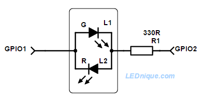
How did you do the testing? Did you change GPIO pins, apply changes and then "save and restart"? Remember that the LED by default is always OFF - to really test you can go to the "module" config page and set LED function="Find" and hit apply - it should start blinking.
kodacy
commented
2 years ago I tested the continuity from left pin of the led to pin 12 and it is fully connected. and from the right pin to Resistance 561 then Resistance 561 is connected to pin 11. If i test the continuity form right led pin to pin 11 directly i don't have a connection due to the resistance.
Or maybe the red Led might be damaged with all the testing.
ljalves
commented
2 years ago The latest firmware (1v1) supports 2 independent leds but it would be nice if you could do some tests with the dual color led you have (I don't think it is damaged).
Select you device first (S20) in the config to set GPIO pins (save and reboot). Then set LED 1 to "Find" and LED2 to "Off" -> see if any color blinks. Then swap settings (LED 1 to "Off" and LED2 to "Find") - > check if the other color blinks.
If nothing happens, change to "custom" device and set "Active low" on both LEDs and repeat the above test.
Let me know how it goes. If any of these tests work I can add proper support for it.
kodacy
commented
2 years ago When I set Device Type to Wiwo-s20 Led 1 find Led 2 off = blue blink Led 1 off Led 2 find = No light
BTW increased the Button debounce time Recovery timer and Recovery # of toggles for more stable work
kodacy
commented
2 years ago On "custom" device and set "Active low" on both LEDs the resolt is similar but in inverted positions red Led never blinks
 NesporBellisRM
commented
2 years ago
NesporBellisRM
commented
2 years ago Added first - thank you. This brings life back to some much older / harder to integrate kit into a more up to date HA set-up, please take none of the following as criticism in any way what so ever.
So... firstly to add - I can attest that I am able to flash both the UK and the EU variants of the Orvibo/wiwo S20. I first use a serial flash to get the default HF firmware ( both application and wifi ) and then use the OTA method to use the hfeasy firmware, so far so good. I have selected the wiwo-20 as the device type.
Problems issues seen so far - I do happen to use a WPA2/AES password that is 63 characters long, this does not take when entered in the GUI - I assume there is a hard coded shorter limit ( 32 characters? ) maybe in the wifi stack so cannot be changed? Similarly for MQQT I have a 100 character password ( Home Assistant / carry over from user login ) which will not take - I believe this is in the hfeasy code and currently has a hard coded shorter limit as well, for this I have created another user with a shorter password as a work around but maybe something to look at ( this is up against Tasmota which can handle the longer passwords for wifi / mqqt without issue ) a "will not fix" could be appropriate if there are hardware limitations that you are up against here.
I see the same issues around the LED as above. Blue LED seems to be not a problem it can be set / flash etc. all appropriately, button works to change the relay state. It would be great to get the dual colours working so that there is a visual indication that the socket is powered / connected to wifi as well as when the socket is on - similar to how it is with the default Orvibo firmware - something like blue when plugged in / on wifi which changes to red when the relay is on as well.
How can I help to debug this further?
Visually the UK boards are identical to the EU one, the serial flash was done by soldering pin-header into the GND/TX/RX holes and the VCC hole ( data sheet says VCC should be 3.3v not 5v :) ) and hooking up a standard TTL<>USB adapter to a mac ( in this case ) machine and using a terminal that can xmodem files out.
NesporBellisRM
commented
1 year ago Adding to the circuit tracing above:
Pin 12 ( PWM2 ) ----- + |>-----RESISTOR---- Pin 11 ( PWM1 ) Red LED forward voltage 1.92V Pin 11 ( PWM1 ) -----RESISTOR----+|>-------Pin 12 ( PWM2 ) Blue LED forward voltage 2.75V
An "expected" behaviour would be to have no LED lit when the plug is neither connected to wifi and the relay is off, one colour LED ( say blue ) lit when the relay is off and wifi is connected, and finally the other LED ( say red ) lit when the relay is on. Being a dual diode the colours are ( of course ) mutually exclusive so the over-riding LED should be the one that shows the relay is on irrelevant of wifi status.
So an example of and ideal start up:
Swap blue / red as appropriate above - not wedded to either colour for a specific function.
I hope this is helpful.
 riogrande75
commented
11 months ago
riogrande75
commented
11 months ago Any update on the LED issue?
I've flashed my S20 with this nice fw and included it in HA. If LED's would work as well like @NesporBellisRM desired, it would be awesome.
Hi Luís thank you for all your work on this project.
I have Fashed though UART//Seral and Orvibo S20 WiWo-S20-E2 with the original HF software since this module is based on a HF-LPB100. Was able to configure the WF-Fi connectivity though the Http interface and connect it to my network. as was even able to install your firmware and i can see the configure and control pages. but when I send the command to change the sate or press it does not activate the relay. Also the led (blue/red) do not work (ever with the HF software) and the physical button on the plug resets the device and disconnectes it from the network.
I believe the relay, button and Leds on the Orvibo S20 might be connected to different GPIO pins on the HF-LPB100 when comparing to Ankuoo models. If you can tell me the GPIO used by your firmware I trace the lines on the S20 and find the differences.
In alternative maybe I'm missing some part of the S20 software to control the relay / led / button they have on-board.
any suggestion how to make Orvibo S20 work with HFeasy?