Closed uldara1 closed 1 year ago
@uldara1 You will need to copy the existing panel class and create Panel_RM68120.h.
If the communication specifications are similar to other 16-bit parallel panels, it will probably work if only the initialization command sequence is prepared.
If there are differences in communication specifications, you may need to implement overrides for various functions as needed.
I have now added Panel_RM68120 to the experimental branch. However, I have not confirmed that it works. Please give it a try if you are so inclined. If you find something that needs to be adjusted, please try modifying it based on this.
@lovyan03 i have try your code already but screen not work pls check my configuration are correct or not my Device is ESP32 S3 HMI Kit 16 bit LCD
`#define FUNC_LCD_EN 1
class LGFX : public lgfx::LGFX_Device
{
lgfx::Light_PWM _light_instance;
lgfx::Panel_RM68120 _panel_instance;
lgfx::Bus_Parallel16 _bus_instance; // 8ビットパラレルバスのインスタンス (ESP32のみ)
//lgfx::Touch_GSLx680_320x320 _touch_instance;
public:
LGFX(void)
{
{ // バス制御の設定を行います。
auto cfg = _bus_instance.config(); // バス設定用の構造体を取得します。
// 16位设置
//cfg.i2s_port = I2S_NUM_0; // 使用するI2Sポートを選択 (0 or 1) (ESP32のI2S LCDモードを使用します)
//cfg.freq_write =1000000; // 送信クロック (最大20MHz, 80MHzを整数で割った値に丸められます)
cfg.pin_wr = GPIO_LCD_WR; // WR を接続しているピン番号
cfg.pin_rd = GPIO_LCD_RD; // RD を接続しているピン番号
cfg.pin_rs = GPIO_LCD_RS; // RS(D/C)を接続しているピン番号
cfg.pin_d0 = GPIO_LCD_D00;
cfg.pin_d1 = GPIO_LCD_D01;
cfg.pin_d2 = GPIO_LCD_D02;
cfg.pin_d3 = GPIO_LCD_D03;
cfg.pin_d4 = GPIO_LCD_D04;
cfg.pin_d5 = GPIO_LCD_D05;
cfg.pin_d6 = GPIO_LCD_D06;
cfg.pin_d7 = GPIO_LCD_D07;
cfg.pin_d8 = GPIO_LCD_D08;
cfg.pin_d9 = GPIO_LCD_D09;
cfg.pin_d10 = GPIO_LCD_D10;
cfg.pin_d11 = GPIO_LCD_D11;
cfg.pin_d12 = GPIO_LCD_D12;
cfg.pin_d13 = GPIO_LCD_D13;
cfg.pin_d14 = GPIO_LCD_D14;
cfg.pin_d15 = GPIO_LCD_D15;
_bus_instance.config(cfg); // 設定値をバスに反映します。
_panel_instance.setBus(&_bus_instance); // バスをパネルにセットします。
}
{ // 表示パネル制御の設定を行います。
auto cfg = _panel_instance.config(); // 表示パネル設定用の構造体を取得します。
cfg.pin_cs = GPIO_LCD_CS; // CS要拉低
cfg.pin_rst = GPIO_LCD_RST; // RST和开发板RST相连
cfg.pin_busy = -1; // BUSYが接続されているピン番号 (-1 = disable)
// ※ 以下の設定値はパネル毎に一般的な初期値が設定されていますので、不明な項目はコメントアウトして試してみてください。
cfg.panel_width = LCD_WIDTH; // 実際に表示可能な幅
cfg.panel_height = LCD_HEIGHT; // 実際に表示可能な高さ
// cfg.offset_x = 0; // パネルのX方向オフセット量 // cfg.offset_y = 0; // パネルのY方向オフセット量 // cfg.offset_rotation = 0; // 回転方向の値のオフセット 0~7 (4~7は上下反転) // cfg.dummy_read_pixel = 8; // ピクセル読出し前のダミーリードのビット数 // cfg.dummy_read_bits = 0; // ピクセル以外のデータ読出し前のダミーリードのビット数 // cfg.readable = false; // データ読出しが可能な場合 trueに設定 // cfg.invert = true; // パネルの明暗が反転してしまう場合 trueに設定 // cfg.rgb_order = false; // パネルの赤と青が入れ替わってしまう場合 trueに設定 cfg.dlen_16bit = true; // データ長を16bit単位で送信するパネルの場合 trueに設定 cfg.bus_shared = false; // SDカードとバスを共有している場合 trueに設定(drawJpgFile等でバス制御を行います)
_panel_instance.config(cfg);
}
setPanel(&_panel_instance); // 使用するパネルをセットします。
} };
LGFX tft;
void setup() { // put your setup code here, to run once: tft.begin(); tft.setRotation(0); tft.fillScreen(0xFFFFFFu);
}
void loop() { // put your main code here, to run repeatedly:
}`
I don't know because I don't know the specifications of that product. You should provide a url with the product specs.
Also, do you have a logic analyzer? If you have one, can you check if the signal is being output?
I do not have the RM68120 so I cannot debug. To some extent you will have to investigate the problem yourself.
Does the backlight glow? If your board requires a separate backlight control, that control may need to be done by you.
yeah backlight glow, and i check your LCD Req should be fine. but lcd not display anything, i don't have logic probe to test signal output from BusParrallel or not
@lovyan03
this is product that i use https://nl.aliexpress.com/item/1005003814428825.html?gatewayAdapt=glo2nld github: https://github.com/W00ng/ESP32-S3-HMI-DevKit SCH-esp..80.pdf
Hi @lovyan03
i found in your library pin order start from 8-15, 0-7 so i try to change my pin configure as your reference and screen shown white but we can't change color to screen by using .fillScreen(0xff0000u) and other command not work too
I was able to find the point where it needed to be implemented, so I updated the experimental branch. Please restore the pin settings and try again.
Hi @lovyan03 i have try this already but screen not display ,glow only backlight
Dear @lovyan03 i just got logic analyzer i try with esp idf from command
esp_lcd_panel_io_tx_param(io, 0xF000, (uint16_t[]) {0x55,}, 2);
it work and have signal output
but when i used with your command it's not work and no signal output
writeRegister(0x00ff, 0x55);
please check my feedback thank
@uldara1 Sorry for the inconvenience.
The panel we ordered from AliExpress has arrived and we will be verifying the actual device soon.
@uldara1 Thank you for your patience. I have updated the develop branch. RM68120 is now available. I added lgfx_user/LGFX_ESP32S3_wywy_ESP32HMI.h to the example configuration. Please try it and see.
Dear @lovyan03
It's working now Thank for your activity 🥰
@uldara1 I appreciate your work to make sure it works. I am glad it works well !
If there are no other issues, you can close this Issue.
@uldara1 I appreciate your sponsorship ! Thank you !
@lovyan03 thank for your hard working too :D
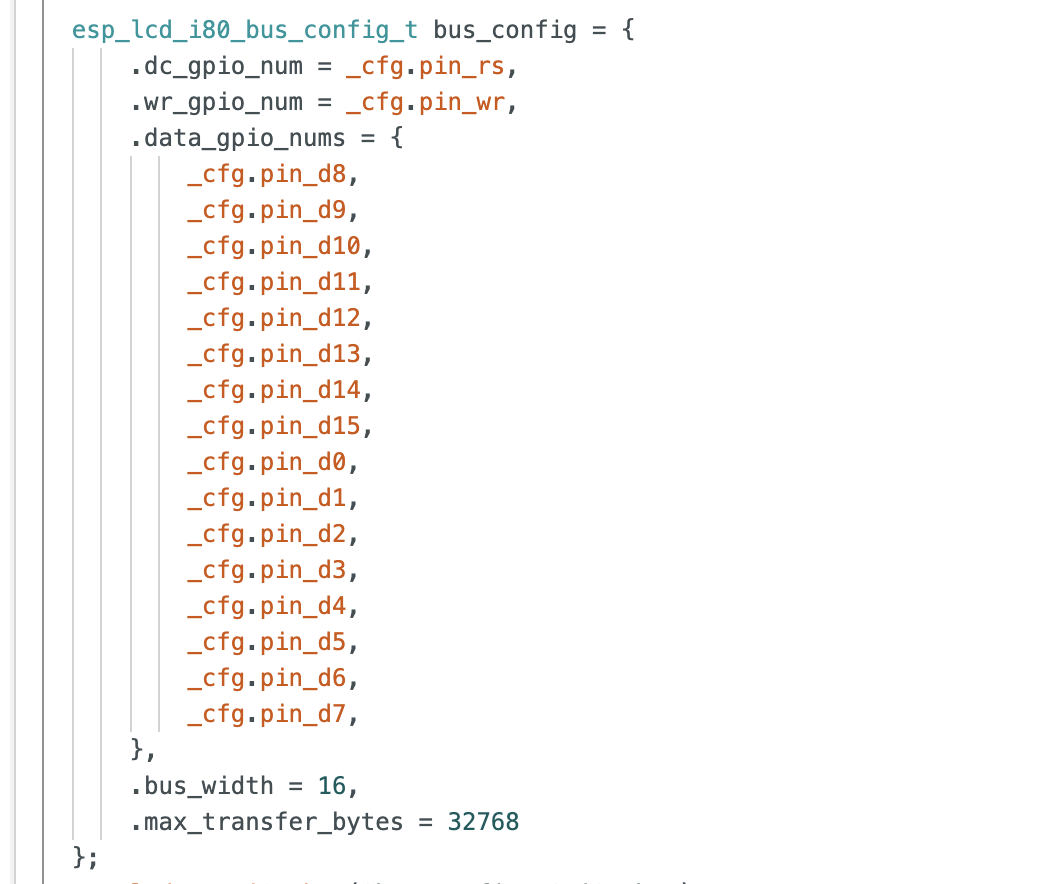
Hello sir @lovyan03 i plant to use Bus_Parallel16 directly to my LCD "RM68120" , is it possible ? i found some header for RM68120 from ESP IDF and i want to use it your library . if can pls show how to use thank you :D