 lovyan03
commented
1 year ago
lovyan03
commented
1 year ago Your code is set up to use FT5x06. The FT5x06 should be an I2C connection, not SPI. I think the touch panel pin settings are duplicating the LCD pin settings and therefore will not work.
Please remove the touch panel settings first.
 osugiw
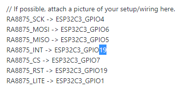


 tobozo
 github-actions[bot]
Carefully written Issues are more likely to be given priority. 丁寧に記述された報告は優先して対応される可能性が高くなります。
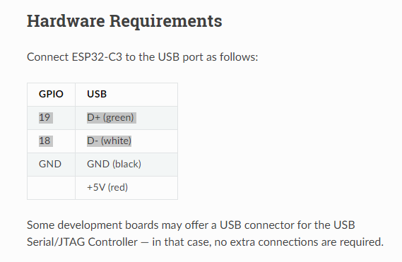
Environment ( 実行環境 )
Problem Description ( 問題の内容 )
The program compiled successfully but display nothing in the RA8875 or print error state in terminal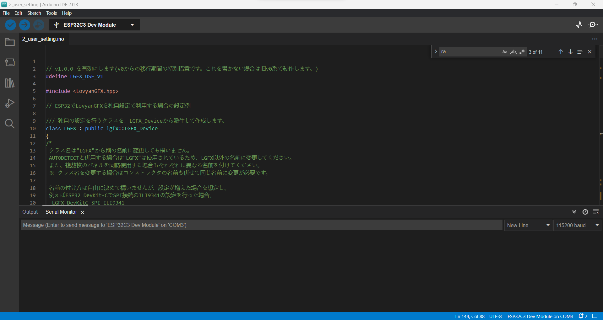
Expected Behavior ( 期待される動作 )
Display text and colour
Actual Behavior ( 実際の動作 )
Display nothing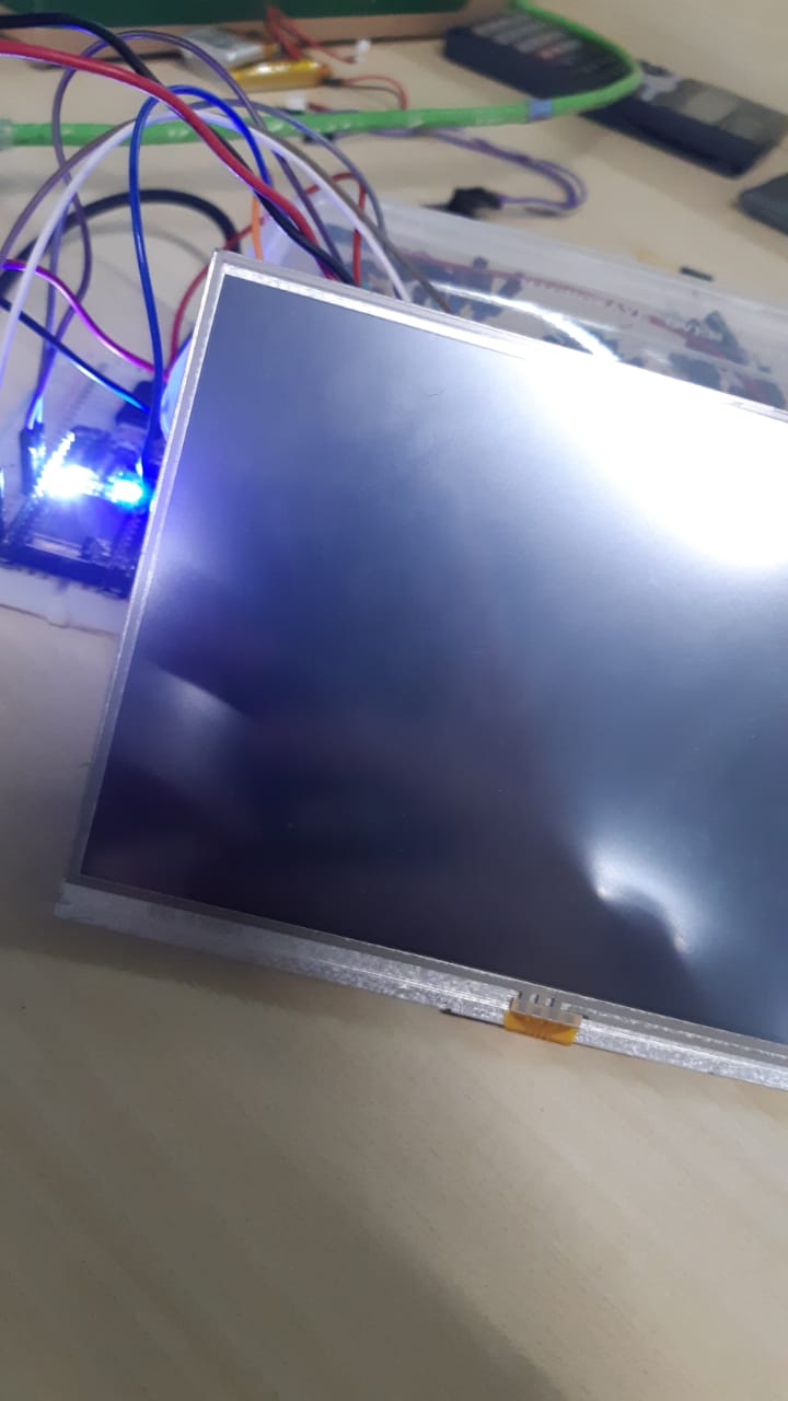
Steps to reproduce ( 再現のための前提条件 )
// If possible, attach a picture of your setup/wiring here. RA8875_SCK -> ESP32C3_GPIO4 RA8875_MOSI -> ESP32C3_GPIO6 RA8875_MISO -> ESP32C3_GPIO5 RA8875_INT -> ESP32C3_GPIO18 RA8875_CS -> ESP32C3_GPIO7 RA8875_RST -> ESP32C3_GPIO19 RA8875_LITE -> ESP32C3_GPIO1
Code to reproduce this issue ( 再現させるためのコード )
https://gist.github.com/osugiw/87b9a042b99295b1686c8a33c28fbc07