 lovyan03
commented
10 months ago
lovyan03
commented
10 months ago あなたの設定がわからないですが、クロックを下げてみてはどうですか? あるいは配線の状態が悪いかも知れませんね。
Closed ThePonFarr closed 9 months ago
lovyan03
commented
10 months ago あなたの設定がわからないですが、クロックを下げてみてはどうですか? あるいは配線の状態が悪いかも知れませんね。
 ThePonFarr
commented
10 months ago
ThePonFarr
commented
10 months ago Thanks for your response. I tried lowering clock speed but it doesn't make a difference. Here is my setup code. When I do: // LCD1.fillScreen(TFT_RED); or any other color it works perfectly.
public:

  // コンストラクタを作成し、ここで各種設定を行います。
  // クラス名を変更した場合はコンストラクタも同じ名前を指定してください。
  LGFX(void)
  {
    { // バス制御の設定を行います。
      auto cfg = _bus_instance.config();    // バス設定用の構造体を取得します。

// SPIバスの設定
      cfg.spi_host = SPI2_HOST;     // 使用するSPIを選択  ESP32-S2,C3 : SPI2_HOST or SPI3_HOST / ESP32 : VSPI_HOST or HSPI_HOST
      // ※ ESP-IDFバージョンアップに伴い、VSPI_HOST , HSPI_HOSTの記述は非推奨になるため、エラーが出る場合は代わりにSPI2_HOST , SPI3_HOSTを使用してください。
      cfg.spi_mode = 0;             // SPI通信モードを設定 (0 ~ 3)
      cfg.freq_write = 40000000;    // 送信時のSPIクロック (最大80MHz, 80MHzを整数で割った値に丸められます)
      cfg.freq_read  = 16000000;    // 受信時のSPIクロック
      cfg.spi_3wire  = false;        // 受信をMOSIピンで行う場合はtrueを設定
      cfg.use_lock   = false;        // トランザクションロックを使用する場合はtrueを設定
      cfg.dma_channel =SPI_DMA_CH_AUTO; // 使用するDMAチャンネルを設定 (0=DMA不使用 / 1=1ch / 2=ch / SPI_DMA_CH_AUTO=自動設定)
      // ※ ESP-IDFバージョンアップに伴い、DMAチャンネルはSPI_DMA_CH_AUTO(自動設定)が推奨になりました。1ch,2chの指定は非推奨になります。
      cfg.pin_sclk = 12;            // SPIのSCLKピン番号を設定
      cfg.pin_mosi = 11;            // SPIのMOSIピン番号を設定
      cfg.pin_miso = 13;            // SPIのMISOピン番号を設定 (-1 = disable)
      cfg.pin_dc   = 3;            // SPIのD/Cピン番号を設定  (-1 = disable)
     // SDカードと共通のSPIバスを使う場合、MISOは省略せず必ず設定してください。
//*/
/*
// I2Cバスの設定
      cfg.i2c_port    = 0;          // 使用するI2Cポートを選択 (0 or 1)
      cfg.freq_write  = 400000;     // 送信時のクロック
      cfg.freq_read   = 400000;     // 受信時のクロック
      cfg.pin_sda     = 21;         // SDAを接続しているピン番号
      cfg.pin_scl     = 22;         // SCLを接続しているピン番号
      cfg.i2c_addr    = 0x3C;       // I2Cデバイスのアドレス
//*/
/*
// 8ビットパラレルバスの設定
      cfg.i2s_port = I2S_NUM_0;     // 使用するI2Sポートを選択 (I2S_NUM_0 or I2S_NUM_1) (ESP32のI2S LCDモードを使用します)
      cfg.freq_write = 20000000;    // 送信クロック (最大20MHz, 80MHzを整数で割った値に丸められます)
      cfg.pin_wr =  4;              // WR を接続しているピン番号
      cfg.pin_rd =  2;              // RD を接続しているピン番号
      cfg.pin_rs = 15;              // RS(D/C)を接続しているピン番号
      cfg.pin_d0 = 12;              // D0を接続しているピン番号
      cfg.pin_d1 = 13;              // D1を接続しているピン番号
      cfg.pin_d2 = 26;              // D2を接続しているピン番号
      cfg.pin_d3 = 25;              // D3を接続しているピン番号
      cfg.pin_d4 = 17;              // D4を接続しているピン番号
      cfg.pin_d5 = 16;              // D5を接続しているピン番号
      cfg.pin_d6 = 27;              // D6を接続しているピン番号
      cfg.pin_d7 = 14;              // D7を接続しているピン番号
//*/

      _bus_instance.config(cfg);    // 設定値をバスに反映します。
      _panel_instance.setBus(&_bus_instance);      // バスをパネルにセットします。
    }

    { // 表示パネル制御の設定を行います。
      auto cfg = _panel_instance.config();    // 表示パネル設定用の構造体を取得します。

      cfg.pin_cs           =    8;  // CSが接続されているピン番号   (-1 = disable)
      cfg.pin_rst          =    -1;  // RSTが接続されているピン番号  (-1 = disable)
      cfg.pin_busy         =    -1;  // BUSYが接続されているピン番号 (-1 = disable)

      // ※ 以下の設定値はパネル毎に一般的な初期値が設定されていますので、不明な項目はコメントアウトして試してみてください。

      cfg.panel_width      =   128;  // 実際に表示可能な幅
      cfg.panel_height     =   128;  // 実際に表示可能な高さ
      cfg.offset_x         =     0;  // パネルのX方向オフセット量
      cfg.offset_y         =     13;  // パネルのY方向オフセット量
      cfg.offset_rotation  =     4;  // 回転方向の値のオフセット 0~7 (4~7は上下反転)
      cfg.dummy_read_pixel =     16;  // ピクセル読出し前のダミーリードのビット数
      cfg.dummy_read_bits  =     1;  // ピクセル以外のデータ読出し前のダミーリードのビット数
      cfg.readable         =  true;  // データ読出しが可能な場合 trueに設定
      cfg.invert           = false;  // パネルの明暗が反転してしまう場合 trueに設定
      cfg.rgb_order        = false;  // パネルの赤と青が入れ替わってしまう場合 trueに設定
      cfg.dlen_16bit       = false;  // 16bitパラレルやSPIでデータ長を16bit単位で送信するパネルの場合 trueに設定
      cfg.bus_shared       =  false;  // SDカードとバスを共有している場合 trueに設定(drawJpgFile等でバス制御を行います)

   cfg.memory_width     =   128;  // ドライバICがサポートしている最大の幅
   cfg.memory_height    =   128;  // ドライバICがサポートしている最大の高さ

      _panel_instance.config(cfg);
画像データが破損していないか確認できますか?
lovyan03
commented
10 months ago ハードウェアの構成がわかりませんが、同じバスにSDカードが接続されていませんか? もしSDカードが繋がっているのであれば、カードを外して確認してください。
ThePonFarr
commented
10 months ago Can you check if the image data is damaged?
The image data is generated through the tool I linked. You can see the original there is correct in "Preview" section.
I don't know your hardware configuration, but is your SD card connected to the same bus? If the SD card is connected, remove the card and check.
I'm not using an SD card. The only other thing on the SPI bus is the on-die 8MB PSRAM. I just disabled through the menuconfig, and tried again. No difference.
Could this be an issue with the init sequence? Maybe it's different for this display, even though it's a GC9107?
There in the product page is the link for the init sequence. It seems a little different compared to what is in the library.
WriteComm(0xFE);
WriteComm(0xEF);

WriteComm(0xB0);
WriteData(0xC0);

WriteComm(0xB2);
WriteData(0x25);

WriteComm(0xB3);
WriteData(0x03);

WriteComm(0xB7);
WriteData(0x01);

WriteComm(0xB6);
WriteData(0x19);

WriteComm(0xAC);
WriteData(0xCB);
WriteComm(0xAB);
WriteData(0x0f);
WriteComm(0x3A);
WriteData(0x05);

WriteComm(0xB4);
WriteData(0x04);

WriteComm(0xA8);
WriteData(0x08);

WriteComm(0xb8);
WriteData(0x08);

WriteComm(0xea);
WriteData(0x4f);

WriteComm(0xe8);
WriteData(0x2C);

WriteComm(0xc6);
WriteData(0x21);

WriteComm(0xc7);
WriteData(0x12);

WriteComm(0xF0);
WriteData(0x09);
WriteData(0x29);
WriteData(0x08);
WriteData(0x39);
WriteData(0xA4);
WriteData(0x1F);
WriteData(0x13);
WriteData(0x60);
WriteData(0x00);
WriteData(0x08);
WriteData(0x08);
WriteData(0x16);
WriteData(0x10);
WriteData(0x1F);

WriteComm(0xF1);
WriteData(0x17);
WriteData(0x2A);
WriteData(0x58);
WriteData(0x3E);
WriteData(0xd6);
WriteData(0x16);
WriteData(0x3f);
WriteData(0x60);
WriteData(0x04);
WriteData(0x06);
WriteData(0x0D);
WriteData(0x1f);
WriteData(0x1c);
WriteData(0x10);

 //WriteComm(0x21);

WriteComm(0x11);
Delay(120);
WriteComm(0x29);
Delay(120);    */

WriteComm(0xFE);
WriteComm(0xEF);

WriteComm(0xB0);
WriteData(0xC0);

WriteComm(0xB1);
WriteData(0x80);

WriteComm(0xB2);
WriteData(0x27);

WriteComm(0xB3);
WriteData(0x13);

WriteComm(0xB6);
WriteData(0x19);

WriteComm(0xB7);
WriteData(0x05);

WriteComm(0xAC);
WriteData(0xC8);

WriteComm(0xAB);
WriteData(0x0f);

WriteComm(0x3A);
WriteData(0x05);

WriteComm(0xB4);
WriteData(0x04);

WriteComm(0xA8);
WriteData(0x0a);

WriteComm(0xB8);
WriteData(0x08);

WriteComm(0xEA);
WriteData(0x02);

WriteComm(0xE8);
WriteData(0x2A);

WriteComm(0xE9);
WriteData(0x47);

WriteComm(0xE7);
WriteData(0x5F);

WriteComm(0xC6);
WriteData(0x21);

WriteComm(0xC7);
WriteData(0x13);

WriteComm(0xF0);
WriteData(0x1D);
WriteData(0x38);
WriteData(0x09);
WriteData(0x4D);
WriteData(0x92);
WriteData(0x2F);
WriteData(0x35);
WriteData(0x52);
WriteData(0x1E);
WriteData(0x0C);
WriteData(0x04);
WriteData(0x12);
WriteData(0x14);
WriteData(0x1F);

WriteComm(0xF1);
WriteData(0x16);
WriteData(0x40);
WriteData(0x1C);
WriteData(0x54);
WriteData(0xA9);
WriteData(0x2D);
WriteData(0x2E);
WriteData(0x56);
WriteData(0x10);
WriteData(0x0D);
WriteData(0x0C);
WriteData(0x1A);
WriteData(0x14);
WriteData(0x1E);

WriteComm(0xF4);
WriteData(0x00);
WriteData(0x00);
WriteData(0xFF);

WriteComm(0xBA);
WriteData(0xFF);
WriteData(0xFF);

WriteComm(0x11);
Delay(120);
WriteComm(0x29);

  /*
WriteComm(0x11);
Delay(480);//Delay 120ms
 tobozo
commented
10 months ago
tobozo
commented
10 months ago some thoughts:
ThePonFarr
commented
10 months ago some thoughts:
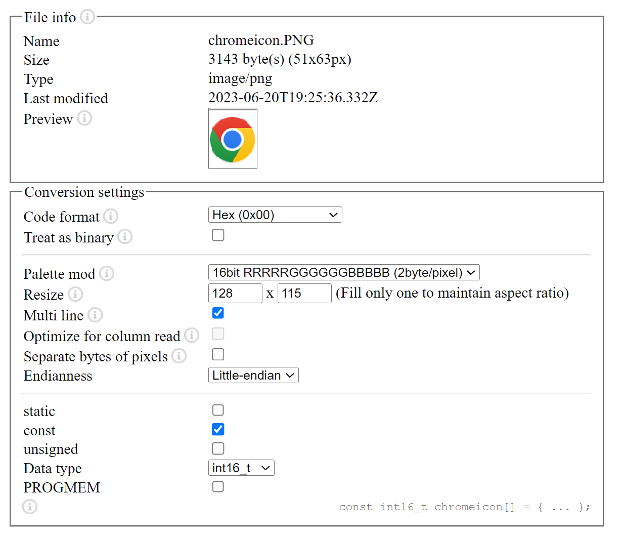
- the tool also resizes the image, this may create artefacts, suggestion: test without resizing
- the data type chosen in the conversion tool is int16_t but pushImage prefers uint16_t
- setSwapBytes() isn't necessary if proper endiannesss in the conversion tool is chosen
Hi bozo. Thanks for your reply. I went ahead and resized the image to 128x115 manually in GIMP, and re-converted it using the tool without resizing. I also switched to Big-endian notation in the tool, but I don't see a difference. The "Data type" doesn't actually do anything, but i am using uint16_t anyway.
My guess is the problem still involves the init sequence, but I'm completely unfamiliar with how they work. I'd be willing to drop a donation for anyone who is interested in fixing this.
tobozo
commented
10 months ago unless you can send an exact copy of this display to someone interested in your offer, the best donation you can do is test your own init sequence and share the results here, here's how you can do it:
1) open this file in your text editor
2) look at the values under static constexpr uint8_t list0[] in your panel block as if you were in an excel document
WriteCommvalueWriteData values (1 or more), except for 0+CMD_INIT_DELAY where it's a delay in milliseconds (0-255)WriteDatavaluesExample with the gamma settings (0xF0 and 0xF1, both have 14 values) :
Vendor Gamma Settings
WriteComm(0xF0);
WriteData(0x09);
WriteData(0x29);
WriteData(0x08);
WriteData(0x39);
WriteData(0xA4);
WriteData(0x1F);
WriteData(0x13);
WriteData(0x60);
WriteData(0x00);
WriteData(0x08);
WriteData(0x08);
WriteData(0x16);
WriteData(0x10);
WriteData(0x1F);

WriteComm(0xF1);
WriteData(0x17);
WriteData(0x2A);
WriteData(0x58);
WriteData(0x3E);
WriteData(0xd6);
WriteData(0x16);
WriteData(0x3f);
WriteData(0x60);
WriteData(0x04);
WriteData(0x06);
WriteData(0x0D);
WriteData(0x1f);
WriteData(0x1c);
WriteData(0x10);
LGFX Default Gamma settings:
        0xF0, 14, 0x1F,0x28,0x04,0x3E,0x2A,0x2E,0x20,0x00,0x0C,0x06,0x00,0x1C,0x1F,0x0f,
        0xF1, 14, 0X00,0X2D,0X2F,0X3C,0X6F,0X1C,0X0B,0X00,0X00,0X00,0X07,0X0D,0X11,0X0f,
3) start by replacing the default gamma settings with those from the vendor and observe the results
4) play with other values according to the datasheet
If you believe a config value is missing from the default init sequence, you can insert it before the gamma settings in the array.
Example with 0x3h (COLMOD: Pixel Format Set):
Vendor command:
WriteComm(0x3A);
WriteData(0x05);
LGFX command:
0x3a, 1, 0x05,あなたは変換後のデータを提示していない。 私はあなたと同じプログラムを動作させることができない。 従って私があなたのために出来る事は何もありません。
ThePonFarr
commented
10 months ago あなたは変換後のデータを提示していない。 私はあなたと同じプログラムを動作させることができない。 従って私があなたのために出来る事は何もありません。
Hi lovyan. Here, I've created a gist with the converted ICON data. I'm interested to see how it appears on your test device. Let me know:
https://gist.github.com/ThePonFarr/882281151c9eff27f9080eaf91ad8bfa
lovyan03
commented
10 months ago そのデータは正常であることが確認できました。 ですが他の箇所に問題がないことは確認できていません。 現象を再現できる完全にビルドできるコードを提供して欲しいです。 時間の無駄なので。
lovyan03
commented
10 months ago lovyan03
commented
9 months ago GC9107を搭載しているM5StackATOMS3では問題なく表示できています。
ハードウェアに問題がないことを調べて欲しい。 他のライブラリを使って正しく表示できるか試してください。
ThePonFarr
commented
9 months ago hello,
thanks for all of your help. This was a bug in my code. Sorry for taking up your time!
tobozo
commented
9 months ago @ThePonFarr can you please explain the bug to prevent this thread to become a mystery? 😉
Carefully written Issues are more likely to be given priority. 丁寧に記述された報告は優先して対応される可能性が高くなります。
Environment ( 実行環境 )
Problem Description ( 問題の内容 )
I am using the GC9107 panel within the Panel_GC9A01.hpp file. When I use pushImage, the image gets drawn to the display but it seems there are wrong colors in some areas.
I am using the below display.
https://www.osptek.com/products/1/4/264?spm=a2700.12243863.0.0.2ce83e5f4lRpRN
I am using the below site to generate the image array:
https://notisrac.github.io/FileToCArray/
Expected Behavior ( 期待される動作 )
Image should be drawn clearly and accurately.
Actual Behavior ( 実際の動作 )
Wrong coloration certain pixel areas.
Steps to reproduce ( 再現のための前提条件 )
Connect a 128x115 GC9107 display and attempt to draw an image.
// If possible, attach a picture of your setup/wiring here.