 lshachar
commented
2 years ago
lshachar
commented
2 years ago Hi Shane, There is no need to connect the 3v3 on the arduino nano to the low level side of the logic level shifter. Thanks for noticing that. (It was a different user who've made that schematic in the first place!)
(edit: the link that is in the Original Post here does not show the aforementioned bug anymore)
 Shane87F3Ng
 ProjectCoops
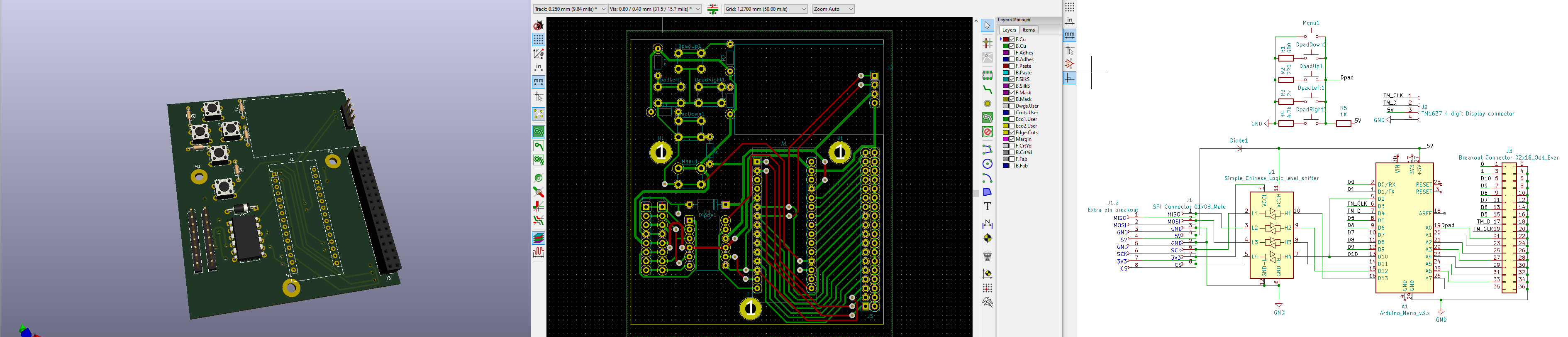
Hi Ishachar,
is it possible, that the schematic shown at
https://github.com/lshachar/Arduino_Fanatec_Wheel/blob/master/schamtics%20arduino%20nano-level%20shifter-fanatec%20round%20plug.png
is not correct (anymore?)?
Because you connect the 3V3 from the Base to the 3V3 connector on the arduino, but in your detailed schematics, this connection line is not shown. So which one is right? :)
Cheers Shane