 mariuszhermansdorfer
commented
3 years ago
mariuszhermansdorfer
commented
3 years ago Here are a few additional screengrabs with the aspect analysis activated to better visualize what is going on.

We can clearly see how the amount of distortion increases towards the edges of the depth map. That's why smart people at Microsoft decided to clip the signal to a hexagonal pattern to avoid unreliable readings. The quasi-horizontal streaks at teh edges correspond to '0' values in the depth map.

To obtain a rectangular image we need to trim off a significant portion from the sides. Approximately 130 columns from left/right and 20 rows from top/bottom. Interestingly, this leaves us with a lower resolution depth image than the Kinect V2. Azure (trimmed): 380x536 = 203,680 pixels Kv2: 512x424 = 217,088 pixels

Maybe using the wide field-of-view mode will help here. I'm skeptical, though, because with increased resolution, comes a massive increase in area covered. Therefore, a pixel per mm ratio will probably be worse in the WFOV compared to the NFOV mode.
While working with undistorted coordinates, the resulting mesh doesn't follow a rectangular outline. The underlying pixels are still ordered in a nice grid, but their corresponding XY coordinates are radially expanding outwards:

A close-up look of the underlying mesh from the Top view:

Also, since our elevation banding logic hasn't been updated yet, we can clearly see the 6 degree tilt of the depth camera in action. The mesh pipeline is being fed corrected Z values, while the coloring function (still) operates on raw data from the depth sensor.

I'm really puzzled about why the depth camera is tilted in relation to the RGB sensor. I simply fail to see the advantage of that setup. Any ideas?
 philipbelesky
@philipbelesky, @BarusXXX let's start a new thread about this.
It took me a while, but I think I've finally wrapped my head around how Kinect Azure understands the world. Here are some important facts:
Transforming from depth camera space to RGB camera space results in the amount of pixels equivalent to current RGB camera mode. This is overkill for our use case, especially if we consider, that the resulting pixels are interpolated, hence don't add any meaningful information (reference)
Transforming from depth camera space directly to a point cloud keeps the amount of pixels and results in undistorted 3D geometry. Under the hood, a lookup table is generated for each 2D depth pixel with a translation vector defining the XYZ coordinates of resulting 3D points. (reference)
Unfortunately, there is a lot of jitter in the depth signal, which results in pixels 'jumping' on the XY plane. To counter for it, we previously used a fixed rectangular grid generated when 'sensorElevation' was set, and subsequently changed only the Z values of this grid. Kinect Azure doesn't have rectangular depth output which makes our task less trivial but we can 'undistort' its depth image by leveraging the lookup table mentioned above (reference)
Once 'sensorElevation' is set (either manually or through the calibration process) we need to calculate the 'ideal' XY spacing of our 3D pixels. The aforementioned camera tilt needs to be taken into consideration here. We generate another lookup table, where we store individual pixel's vertical deviation per unit of Z elevation. Then we create a 'fake' depth map with 'ideal' uniform elevations (this doesn't mean that individual pixel values are identical, but they correspond to a 'flat' plane) and pass it to our transformation logic to obtain 'ideal' XY coordinates for given 'sensorElevation'.
Side view before: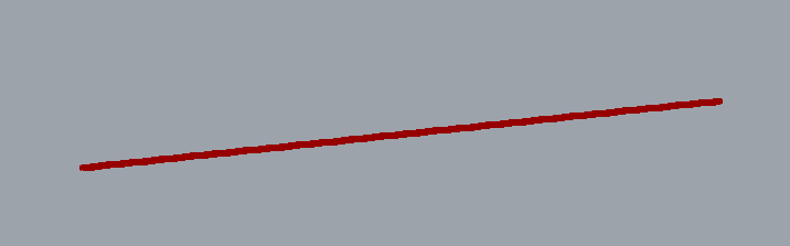
Side view after:
There are some outliers, but it's close enough to accept as final solution: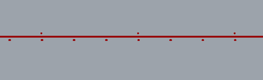
I have a working prototype branch on my machine. Will clean up the code a bit and publish to the repo on Monday.