martin2250 / OpenCNCPilot

autolevelling gcode-sender for grbl
MIT License
377 stars 112 forks source link

CNC Knowledge sharing thread #126

Open gururajkashikar opened 4 years ago

gururajkashikar commented 4 years ago

Hi Martin,

First of all, thank you for this wonderful software. I was able install Grbl 1.1J and use OpenCNCPilot to move all 3 axis using manual mode as well as using Keyboard. Just wanted to make sure that I have met pre-requisites (grbl 1.1 and .NetFrameWork 5).

I was also able to utilize "Probe and set Zero" macro to check if my probing is functioning properly. It is working as expected.

I was trying to use the most awesome part of this software, Probing. But "Run" button is not getting enables. What I am missing here? Could you please throw some light on this. Attaching image of my Screen for your reference.

Thanks in Advance.

Regards, Guru OpenCNCPilot

deHarro commented 
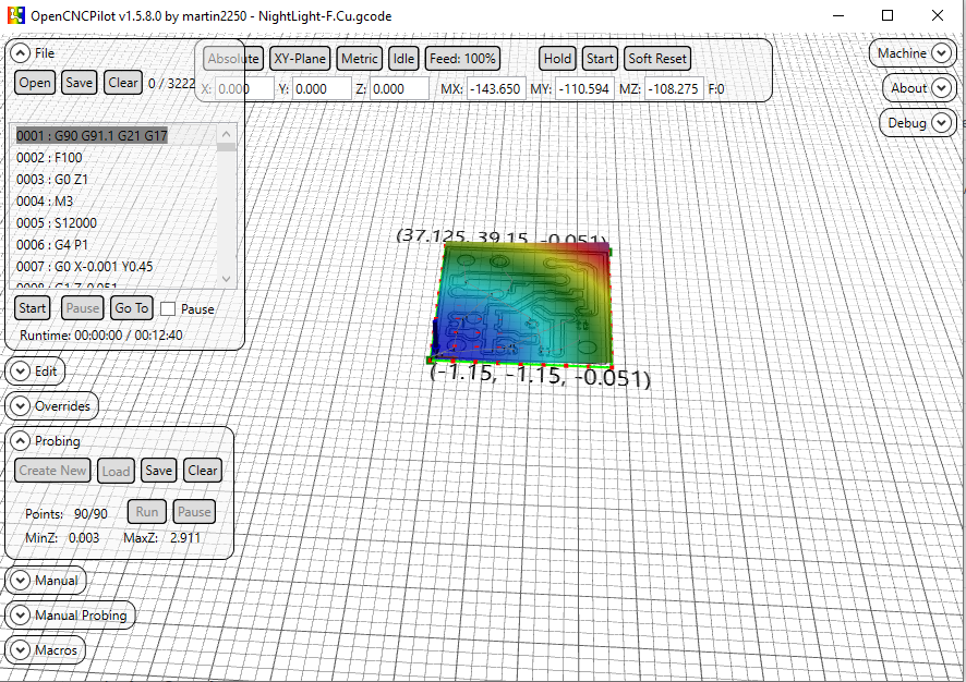
4 years ago

Hi Guru, "Points: 90/90" tells us, that your map is generated already. All 90 points of the map are obviously probed. Next after having done the probing you have to Apply the hight map to your gcode. You find the corresponding button in the "Edit" panel. After having applied the map you can "Start" etching (see "File" panel). Hope that helps.

Harald

gururajkashikar commented 4 years ago

Thanks for the reply Harald. It never probed even a single point. As soon as open probe window, select the area to be probed, the attached screen is what I can see. I can't press the Run button. So no probing of even one point. My CNC stays at 0,0,0 x,y,z respectively. I am missing something.

deHarro commented 4 years ago

What happens if you click "Clear" in Probing panel? Then "Create new" should be activated.

gururajkashikar commented 4 years ago

When clear is clicked, probing area with that 3d effect goes off as expected. When I create new, probing points appears but again the same issue. Run button will be disabled.

tarmon01 commented 4 years ago

Make sure you don’t have the “generate test pattern” box checked and make sure you click on “size from Gcode” once.

-TomH-

On Mar 25, 2020, at 1:08 PM, gururajkashikar notifications@github.com wrote:

 When clear is clicked, probing area with that 3d effect goes off as expected. When I create new, probing points appears but again the same issue. Run button will be disabled.

— You are receiving this because you are subscribed to this thread. Reply to this email directly, view it on GitHub, or unsubscribe.

gururajkashikar commented 4 years ago

Where is the "generate test pattern" box? I tried size from gcode. But did not work. Will try this again tomorrow morning. Thanks for the suggestion

tarmon01 commented 4 years ago

On Probing menu click “clear” Click “Create New” Pops up “New Heightmap” window Make sure “Generate Test pattern” box Is NOT selected Click on “Size from gcode” button Click on Ok

“Run” In probing window should be available to click then.

-TomH-

On Mar 25, 2020, at 1:34 PM, gururajkashikar notifications@github.com wrote:

 Where is the "generate test pattern" box? I tried size from gcode. But did not work. Will try this again tomorrow morning. Thanks for the suggestion

— You are receiving this because you commented. Reply to this email directly, view it on GitHub, or unsubscribe.

gururajkashikar commented 4 years ago

Hi tarmon01,

You were right. "Generate Test pattern" was checked because of which "Run" button was not enabled. Now I was able to probe and mill a sample PCB. Attaching the image of the milled PCB if anyone is interested,

Looks like engraving bit was slightly broken and went bit deeper. I'll try with a new bit. Also I had set the milling depth as 0.6mm in my Gcode. Looks like that can be reduced too.

Also one thing I observed. My's CNC Z was not raising up quite high when it is not suppose to mill. Because of this engraving bit went over some of the circuit track and isolated it. Will need to work on this. Any suggestion on the depth of milling and height of the end mill will be helpful.

Thanks for all the help.

Regards, Guru 20200326_110727

deHarro commented 4 years ago

Hi Guru!

If you use the same bit for probing and for milling (without changing anything at the bit inbetween probing and milling), you don't have to zero Z before probing.

But I take it as good practice to zero Z before starting the probing process.

Concerning the depth, I use 0.08 mm (80µm) to go through the 35µ copper cladding. In theory 0.04µ should be enough, but we deduced the distance the router needs to stop after recognizing the touch event as reason why we need to set the milling depth deeper than that.

Concerning the trenches you milled I propose, you should parametrize some more routes to widen the trenches. I use EAGLE as design tool. There exists an ULP named pcb-gcode.ulp which generates the routing pathes around the traces. This ULP allowes to define the number of additional rounds the bit should do to widen the trench between trace and remaining copper. This at least eases the soldering process (no or at least less chances to make a short).

Hope that helps... Harald

gururajkashikar commented 4 years ago

Hi Harald,

Thanks for your time to update these findings. I am using same bit for probing and milling. I was afraid of breaking the V shaped bit if I don't zero Z. Some time when there are error, we hit soft reset and then press Zero machine, I have got couple of V bits broken due to crashing of my machine. Now, back to update about my findings. My Z was not travelling as expected. When I try to move Z by 10mm, it was just moving only 2 mm. I had recalculate step/mm and now its working fine.

Now I think 0.08mm as you said Harald, would be sufficient to engrave the copper clad.. BTW, I was able to drill my PCB. In some place drill bit (0.7mm) did not go all the way down. In most places it did.

Do we need to do the probing and applying hight map to your drill gcode also? Current PCB looks as attached below. Not very accurate though. But good to go as of now.

Screenshot 2020-03-26 at 9 06 25 PM

BTW, the actual issue I mentioned here, was not an issue. It was lack of my knowledge about this tool. So all other things are general discussion. Please suggest me if its ok to discuss these general thing here or should I close this issue?

deHarro commented 4 years ago

Hi Guru, since I am not sure about the squareness of my router I apply the heightmap also to my drill code. This is convenient if you specify the drill depth so that the board is just drilled through (I use 1,7 mm as drill depth. Together with the double sided adhesive tape I fix my boards with, this gets through and doesn't touch the waste plate (don't know the exact wording for the plate beneath the work piece which prevents the bit to touch the routers surface). If you don't care about the waste plate, you can specifiy the drill depth deeper. In this case you don't need to apply the heightmap to the drill code. The same applies to the milling if you use your router to cut out the finished board.

Concerning your findings about the wrong step/mm on Z, I suggest you should check those parameters for all three axes. You can adjust this in the GRBL settings.

Harald

gururajkashikar commented 4 years ago

Hey Harald,

I normally use a thick double sided tape to stick the copper clad sheet to my waste wood board and then place the wood on my CNC bed. There will be a gap of around 1 to 2 mm between copper clad and the wood board itself. Hence my drill bit goes all the way down but does not touch the waste wood board.

I had found X and Y's steps/mm value and it was accurate. Only Z was missing. Now all three are perfect.

One more update :( I lost a 0.7mm router bit today morning when I was trying to cut the board to required size using my CNC. This was because after milling, I could not do the probing. Lesson learnt: 1) Do probing for all three gcode file i.e 1) Milling (2) Drilling (3) Cutting. 2) Apply the height map to respective Gcode files and save it. 3) Then start milling.

Any other suggestion for milling, drilling and cutting would be appreciated.

Thanks and Regards, Guru

deHarro commented 4 years ago

Hi Guru,

I formerly used that thick tape, too, but found, that using thinner double sided tape results in drastically better results. The thicker version is named "Spiegel-Klebeband" over here in Germany, the thinner version is called "Teppich-Klebeband".

The reason seems tob e, that when probing, the bit stops exactly when it touches the surface. When milling, it implies some force to the board and this thicker tape lets the board give way.

Not sure whether I got you right, but you surely have to probe only once. You can apply this one time probing to all three files, one after the other.

Harald

deHarro commented 4 years ago

This is the correct one This is the wrong version

Harald

tarmon01 commented 4 years ago

A tip.

If you “save” the heightmap file you can “load” It if something goes wrong ( closing opencncpilot by mistake for instance) and then you can apply it to drill/mills on a partially done board when the program is running again. There is also a setting box in the config menu that saves the heightmap file automatically.

-TomH-

On Mar 27, 2020, at 7:39 AM, deHarro notifications@github.com wrote:

 This is the correct one This is the wrong version

Harald

— You are receiving this because you commented. Reply to this email directly, view it on GitHub, or unsubscribe.

gururajkashikar commented 4 years ago

Great tips here. Harald: I'll try tomorrow with thinner tape. I was under assumption that each of the gcode file will have its own height map. Your explanation clarifies that same height map can be used for all three is satisfactory. I'll try it out.

tarmon01 : Very nice to know these option exists. I'll give it a shot tomorrow.

Thanks for all this suggestion.

deHarro commented 4 years ago

Hi Guru,

It if something goes wrong ( closing opencncpilot by mistake for instance) and then you can apply it to drill/mills on a partially done board when the program is running again.

In this case you must carefully zero Z (and obviously X and Y as well ;) again, preferably at the same location as you did it first.

Harald

deHarro commented 4 years ago

Hi Guru,

same height map can be used for all three

Since OCP has no option to avoid probing at already etched places, the possibility to just aim at such areas when probing an already treated board is very likely. So it's sort of mandatory to only probe once.

Harald

gururajkashikar commented 4 years ago

Yeah Got it Harald. Another thing what I follow is, First time I zero all three axis, I store that Machine position using G28.1. Later any time I want to restart, I raise the Z to safe height (like 10mm) and issue command G28 to come back to initial zeroed position. From there on I start all over again.

BTW do you use a different Bit for Engraving and Cutting the board? I saw a video where V shaped bit itself was used to mill and cut the copper clad sheet. I tried with router bit and broke it. The router went deep and stuck there while CNC moved ahead to break the bit..

deHarro commented 4 years ago

Hi Guru, the V-bit must only be used for etching and for spot drill (marking) the holes (spot drill: just touch the surface of the copper clad to mark the position where the cylindrical drill bit then should make the hole).

For milling the board outline I use 1,4 mm (sometimes 1,0 mm) "diamond toothed" or "spiral-toothed" drill bits. The holes are drilled with 0,8 mm or 0,9 mm "diamond toothed" drill bits.

Harald

gururajkashikar commented 4 years ago

Hi Harald and tarmon01, I create another PCB today. Had a different experience. I used 0.08 as the depth for PCB milling/Etching. My probing started from Bottom Left of the board, went horizontally i.e. left to right, then 5mm up right to left so on till it reached Top Right. (Attaching the image to make this clear) PCB

After applying height map, when I engraved the board, I saw that the bit went deeper towards the left of the board, but just touched the board on the right side.

My question to you : Is it need that we need to get probing some how from bottom to top as shown in the video of this website (instead of bottom left to right) to get correct probing height. For earlier board, probing was done from bottom to top as in the video. So I have this doubt.

2) Though I used 0.08mm as the depth, looks like it went deeper on left side of the board. Is this problem due to above question.

Image attached in case you want to see it. Tracks are too thick... PCB_Engraved

Gururaj

tarmon01 commented 4 years ago

Gururaj,

I don’t think it matters where it starts. Martin would know for sure.

I did once do a heightmap, realized I forgot something that grew the board size and did not do a new heightmap, because I already did one, 🧐and the traces looked great until it suddenly they stopped etching correctly when they hit the edge of the heightmap. A learning experience.

I always start my projects in the center of the board. I also go quite a bit deeper with my bit 0.19mm. This for me always seems to work. But I use a 60 degree carbide etching bit. And I am mostly doing 30mil traces which isn’t very fine.

https://www.amazon.com/3-175mm-Engraving-EnPoint-Carbide-Aluminum/dp/B019K5G6AI

I gave up on the really really cheap 30 degree-ish bits as the very tip always seemed to break even if I slowed down the mill down to deathly slow speed.

But the other folks here have had better luck with those bits and could advise better.

Thanks,

-TomH-

On Mar 28, 2020, at 12:11 PM, gururajkashikar notifications@github.com wrote:

 Hi Harald and tarmon01, I create another PCB today. Had a different experience. I used 0.08 as the depth for PCB milling/Etching. My probing started from Bottom Left of the board, went horizontally i.e. left to right, then 5mm up right to left so on till it reached Top Right. (Attaching the image to make this clear)

After applying height map, when I engraved the board, I saw that the bit went deeper towards the left of the board, but just touched the board on the right side.

My question to you : Is it need that we need to get probing some how from bottom to top as shown in the video of this website (instead of bottom left to right) to get correct probing height. For earlier board, probing was done from bottom to top as in the video. So I have this doubt.

Though I used 0.08mm as the depth, looks like it went deeper on left side of the board. Is this problem due to above question. Gururaj

— You are receiving this because you commented. Reply to this email directly, view it on GitHub, or unsubscribe.

gururajkashikar commented 4 years ago

Thanks for the update torman01. I think I need to buy 60 deg bits like you have suggested. What do you use for cutting board to its correct measurement.? Can you please share some pics of boards and your CNC machine. Btw can I know your real name.

tarmon01 commented 4 years ago

My name is Tom😃.

I have designed & built my “Mini-chine “ to use 4 tools without changing bits; A pcb carver bit, A .9mm drill, cutout tool( 2mm but I may change it to 1mm), and a pen plotter. It’s based on several parts of the standard Chinese kits but I’ve had to make several aluminum pieces on my big CNC “Chine” machine. I use a decent spindle for the traces and 2 cheap spindles for drilling/cutout as those 2 functions don’t require the same precision.

Martin has modified openCNCpilot such that it will allow me to pass addition gcodes through so I can make a whole board in one gcode file( but I haven’t tested his changes yet). I do not use double sided tape but I do have a backing board that makes contact to the circuit board with clipboard clamps. I use .19mm for traces and 1.9mm depth for cutting/drilling.

It is not perfect yet.. the x axis has too much backlash that I need to fix. But it is good enough for the moment until I can get around to fixing it. I am also in the process of designing a single Arduino shield instead of the several little boards shown in the pictures above, that work with the controller that came with the kits.

Some things that may help you. These are meant as a helpful comments. Your machine has too much backlash in it, going by the picture you sent. Circles should circles not ovals. Also the alignment of drills to the etching are not centered. Anti- backlash nuts would help assuming you don’t have them on ? If you do have them on, make sure the spring is fully compressed and not loose when you screw them on. Also use precise right angles to ensure that X,Y,and Z are perpendicular although X & Y are less important for you than me as you use doubled sided tape to hold the board on and that is likely not going to be very square. Make sure whatever structure you are using is as stiff/rigid as you can make it. if it wobbles or deforms. That’s not good.. add supports as needed so it does’t move when you push on the moving parts by hand. ( or at least minimize it)

Hopes this helps!

FYI. If you are interested in other things I do, my website is TnRCrafts.com.

Thanks,

-TomH-

On Mar 28, 2020, at 3:13 PM, gururajkashikar notifications@github.com wrote:

 Thanks for the update torman01. I think I need to buy 60 deg bits like you have suggested. What do you use for cutting board to its correct measurement.? Can you please share some pics of boards and your CNC machine. Btw can I know your real name.

— You are receiving this because you commented. Reply to this email directly, view it on GitHub, or unsubscribe.

tarmon01 commented 4 years ago

![F6A9E681-2A1F-4B4E-BF0F-1016FA721204 0CE6DD35-5877-421A-A1CF-479F9B307D00 1CB8A3B0-94EB-4835-9727-50BC63D4F137 84DF5152-5DE2-4E76-B0B5-6FE341CED112

tarmon01 commented 4 years ago

Missing, but alas sideways,🙃 photos for last post

-TomH-

gururajkashikar commented 4 years ago

Hi Tom, Thank you so much. Your machine is impressive. I never thought we can have multiple spindle on a single machine. Looks awesome.

The PCB quality is also excellent.

Regarding my CNC machine, it's home made machine with V slot aluminium profile, v wheels and movement is through timing belt. See the image below. 20200329_071024 I'll surely work on your comment. Since I don't have threaded road and nut for X and Y axis, I need to check how to avoid Anti-backlash. The CNC as whole doesn't shake or wobbles. But moves easily by hand. I need to work on that as well.

Regarding electronics, I have arduino nano on grbl CNC shield v4. One single board with stepper controller on it. Lot of work to do before I get PCB like yours. Thanks for you inputs. It matters a lot at this time

Regards, Guru

martin2250 commented 4 years ago

Hi everybody,

just to chime in and answer a few of the questions:

OpenCNCPilot always chooses the closest point to the current position for probing. This means that the probing pattern can be different from time to time. Assuming your machine doesn't loose steps, different probing orders don't make a difference. If the milling depth varies from side to side, it's always an issue with rigidity, either in the machine or the board. I only recommend tape (over the entire board surface, not just small pieces) to hold down boards, and I'm actually quite surprised that Tom's boards come out that cleanly with just two clamps.

Regarding backlash in your machine: timing belts can be quite good in that regard. My first machine, a Shapeoko 2, also used V-rails and timing belts. The best I could do were 0.4mm traces and 0.8mm pitch SMD components. There are a few catches though:

@tarmon01 impressive setup! How do you manage the multiple Z axes with grbl?

Martin

tarmon01 commented 4 years ago

Guru,

Pretty cool to create what you did! I like the innovation you used on the slides.

The belts work best for a laser engraver which has little resisting force when it moves in x and y directions. A spindle requires a very rigid structure as you don’t want the spindle to tilt in opposition to the direction it is going. Pretty sure that explains the results you are getting.

So if you can get lead screws for x and y, that’s probably the best way to go. If you can’t then using some pulleys and steel wire to Implement something called a “moving knot” in x and y can help to prevent “racking” which is what it is called it when the structure goes out of square ( which it does when carving)

Here is a great site for help and to see others peoples design if you have seen it already

tps://www.cnczone.com/forums/diy-cnc-router-table-machines/

Here’s some info on the “moving knot”

https://m.youtube.com/watch?v=V_RsIIGw0xk

https://www.cnczone.com/forums/diy-cnc-router-table-machines/51485-make-gantry-rock-solid.html

Thanks,

-TomH-

On Mar 28, 2020, at 9:58 PM, gururajkashikar notifications@github.com wrote:

 Hi Tom, Thank you so much. Your machine is impressive. I never thought we can have multiple spindle on a single machine. Looks awesome.

The PCB quality is also excellent.

Regarding my CNC machine, it's home made machine with V slot aluminium profile, v wheels and movement is through timing belt. See the image below.

I'll surely work on your comment. Since I don't have threaded road and nut for X and Y axis, I need to check how to avoid Anti-backlash. The CNC as whole doesn't shake or wobbles. But moves easily by hand. I need to work on that as well.

Regarding electronics, I have arduino nano on grbl CNC shield v4. One single board with stepper controller on it. Lot of work to do before I get PCB like yours. Thanks for you inputs. It matters a lot at this time

Regards, Guru

— You are receiving this because you commented. Reply to this email directly, view it on GitHub, or unsubscribe.

tarmon01 commented 4 years ago

Martin,

There are 4 hold downs. Two clipboard clamps, and two thumbscrews that hold aluminum pieces that overlap the board edges. I One clipboard provides electrical contact for the board probing. The clipboards are spaced apart for the inexpensive copper clad boards to slide between on Amazon.( a little over 100mm I think).

What Grbl doesn’t know about, It can’t complain about< heh>.

Grbl however does support 2 coolant controls as well as work offsets. Which is enough to drive 4 different tools with the proper circuitry and Gcode mods.

If you used belts perhaps Guru can also, I’ll leave that in your capable hands.

Thanks,

-TomH-

On Mar 29, 2020, at 5:20 AM, Martin Pittermann notifications@github.com wrote:

 Hi everybody,

just to chime in and answer a few of the questions:

OpenCNCPilot always chooses the closest point to the current position for probing. This means that the probing pattern can be different from time to time. Assuming your machine doesn't loose steps, different probing orders don't make a difference. If the milling depth varies from side to side, it's always an issue with rigidity, either in the machine or the board. I only recommend tape (over the entire board surface, not just small pieces) to hold down boards, and I'm actually quite surprised that Tom's boards come out that cleanly with just two clamps.

Regarding backlash in your machine: timing belts can be quite good in that regard. My first machine, a Shapeoko 2, also used V-rails and timing belts. The best I could do were 0.4mm traces and 0.8mm pitch SMD components. There are a few catches though:

The rolling resistance of your bearings must be very low. Try disconnecting the motors and adjusting the rollers until XY moves with little to no resistance. The belts mustn't be too cold. My boards turned out worse in winter, even with the machine sitting in my bedroom. Belts tend to 'remember' their shape, so after sitting around for a while, there will be a 'bump' when moving over the resting place. My solution was to un-tension the belts when the machine was not in use. The belts must be tensioned properly of course. @tarmon01 impressive setup! How do you manage the multiple Z axes with grbl?

Martin

— You are receiving this because you were mentioned. Reply to this email directly, view it on GitHub, or unsubscribe.

gururajkashikar commented 4 years ago

slides

Hi Tom,

Thanks for your appreciation. I did not get what you meant by "slides".

I had built three machines with leads screws for all three axis. It was quite huge machine. Only one Stepper was used for Y axis. In this belts based machine, I have used two steppers for Y axis as you can see in the above image. Both these steppers are connected in parallel to drv8825 board. They normally move together. But as you said, I can move one side of Y side, by hand, say by 5mm. This is because, the transparent Acrylic sheet I have used can bend to allow one side to move forward with other one stationary. Hope is this the reason why you are suggesting “moving knot”. I looked at it. I'll plan to do something for this. Many people in the link you shared are suggesting to have stable Frame on either side Y axis. So thinking of creating those frame again either using 1 inch thick wood or Aluminium.

Regarding X axis on which my spindle motor is mounted, is quite sturdy as I have used 20x40 Aluminium profile. The distance between top railing and bottom one is almost 6 CMS. Initially I made it with 20x20 then it was very shaky. Now it is rugged. But I'll surely check it once again. Thanks for the inputs.

Gururaj

gururajkashikar commented 4 years ago

Hi everybody,

just to chime in and answer a few of the questions:

OpenCNCPilot always chooses the closest point to the current position for probing. This means that the probing pattern can be different from time to time. Assuming your machine doesn't loose steps, different probing orders don't make a difference. If the milling depth varies from side to side, it's always an issue with rigidity, either in the machine or the board. I only recommend tape (over the entire board surface, not just small pieces) to hold down boards, and I'm actually quite surprised that Tom's boards come out that cleanly with just two clamps.

Regarding backlash in your machine: timing belts can be quite good in that regard. My first machine, a Shapeoko 2, also used V-rails and timing belts. The best I could do were 0.4mm traces and 0.8mm pitch SMD components. There are a few catches though:

  • The rolling resistance of your bearings must be very low. Try disconnecting the motors and adjusting the rollers until XY moves with little to no resistance.
  • The belts mustn't be too cold. My boards turned out worse in winter, even with the machine sitting in my bedroom.
  • Belts tend to 'remember' their shape, so after sitting around for a while, there will be a 'bump' when moving over the resting place. My solution was to un-tension the belts when the machine was not in use.
  • The belts must be tensioned properly of course.

@tarmon01 impressive setup! How do you manage the multiple Z axes with grbl?

Martin

Hi Martin,

Thanks for jumping in. Great to see you commenting here. Personally I thank you for providing such a good software.

Regarding the direction of probing, I think I made the probing points to be 10 mm apart rather than the default of 5 mm. This may be the reason it chose to move left to right. As suggested by You and Tom, I'll see if there are any problem with rigidity of the board or any issue with my CNC machine itself.

Great to know you had also tried with Timing belt. Please post images of that machine if you had taken. This will help me to get some idea to modify my machine.

Thank you for suggestion regarding timing belt. I was not aware that it becomes rigid or "remembers" the shape. I'll un-tension the belts when I do not use it. Great suggestion.

BTW, I got thin tape as suggested by Harald and tried to stick copper clad Sheet (CCS) to the waste wood board. But it did not stick properly, hence I am using thick double sided tape. But as you have mentioned only small pieces is what I was using. May be this is also contributing to bending the board in the areas where there are no tapes below it. I need to know if there are other ways to make CCS to get rigidly to waste wood.

Tom : Can you please send a close up image of your clamps. I'll try to make one like that.

Thanks all.

Regards, Guru

deHarro commented 4 years ago

Hi Guru, I had the same problems you describe with fastening my boards (board giving way when fastened with thick tape, no good adhesion on wooden waste board).

In the end I fixed all issues concerning probing and fastening by using a 30 mm thick piece of POM, about 20 x 30 cm. I checked with thinner POM plates, but they were not sturdy enough.

This 30 mm material is rigid (no warping) and it accepts the thin double sided tape.

In this closed issue you can see the POM plate I use. Down below in this linked issue is the explanation of Martin, why one should add some microns to the desired carving depth.

Harald

martin2250 commented 4 years ago

Personally I thank you for providing such a good software.

Your're welcome, I'm really glad to see so many people using my Program :)

Please post images of that machine if you had taken

https://google.com/search?q=shapeoko+2&tbm=isch, nothing special about my machine, I just replaced the dremel-type spindle with a proper Kress router.

Also you mentioned somewhere that you use G28.1 to store the zero point. G28 is intended for remembering some point in the machine for changing tools etc. For setting up your workpiece, you should use G10.

gururajkashikar commented 4 years ago

Hi All, At last I was able to cut PCB using router bit of 0.7mm with multi depth option available in flatcam and opencncpilot...See the images. One PCB is for spindle led light and other smallest PCB I have ever created is for pwm to 10v converter to control speed of the same spindle.

20200331_182123

20200331_182145

20200331_200932

20200331_205804

tarmon01 commented 4 years ago

You are using the machine to make the machine better! Cool stuff.

146F1F3B-73D2-4D7E-A0A0-E2D0E37F31EB

Here’s a closeup picture of my hold downs. The thumbscrews are tapped into the aluminum plate that lies underneath the white pvc.

gururajkashikar commented 4 years ago

Hi Tom,

That's pretty impressive. Will it hold the copper clad (CCS) tight so that when CNC engraves, it will not move away? If bottom of the CCS is aluminium, how to you manage to drill and cut the board so that drill bits will not break? Anyways thanks for sharing this close up picture..

Many parts of my machine is created by the machine itself. Like one of its X axis plate was created by itself because I wanted holes to be at exact distance between each other for the sliding wheel.

Regards, -Guru

deHarro commented 4 years ago

Hi Tom!

You are using the machine to make the machine better! Cool stuff.

Freely according to the rule: I use my router to make parts, that without it, I neither were able to make nor would need at all ;-)

In the beginning of my odyssey with my router I encountered this effect heavily myself :-) I think everyone will do. But it's part of the fun.

Harald

tarmon01 commented 4 years ago

Harald, Nicely put! And I agree for sure.

Also to answer Guru’s question, the pvc layer is 3/8” thick ie it’s a “spoiler board”. So the drill never reaches the aluminum. The aluminum plate underneath is as flat as I could make it (plate aluminum not extruded) So even without openCNCPilot I could get usable boards with double sided tape. But with OPenCNCpilot, I can use the spoilerboard many many times and the program takes the bumps from previous cutouts and drill holes from affecting the final result. I may at one point mill it down or sand it. But haven’t needed to yet. BTW. In the picture the thumbscrews are loose. When I tighten them down, it holds the board down very well. Also when I do some mods to the spoiler board to add a right angle on one side, I should be able to do double sided boards fairly easily.

At least that’s the plan.

Thanks,

-TomH-

On Apr 1, 2020, at 10:09 AM, deHarro notifications@github.com wrote:

 Hi Tom!

You are using the machine to make the machine better! Cool stuff.

Freely according to the rule: I use my router to make parts that without it I neither were able to make nor would need at all ;-)

In the beginning of my odyssey with my router I encountered this effect heavily myself :-) I think everyone will do. But it's part of the fun.

Harald

— You are receiving this because you were mentioned. Reply to this email directly, view it on GitHub, or unsubscribe.

gururajkashikar commented 4 years ago

Hi All,

Forgot to ask you one more important point. I was using my machine with bluetooth module connected to grbl Arudino. ChilliPepper is recognising the port used by this bluetooth module (HC-05) and works fine there. But OpenCNCPilot does not accepts the COM ports used by bluetooth module. Only when I connect USB cable between Arduino and Laptop I can use OpenCNCPilot. Any idea how I can use HC-05 to wirelessly use OpenCNCPilot and CNCs

Please shed some light on this.

-Guru

martin2250 commented 4 years ago

Hi Guru,

sorry for the late response. I don't have any Bluetooth modules here for testing this. OpenCNCPilot already combines the output of two different ways to list serial ports on Windows, so I had hoped this would already cover every setup. Since OpenCNCPilot also tries to list serial ports by their names (eg. have a port called "Arduino Uno (COM3)" instead of just "COM3", sadly it isn't possible to enter port names manually. That said, I'm not sure I'd trust a Bluetooth connection to be stable enough for this purpose, maybe it is better to use USB in any case.

Still if anybody with some C# experience and a HC-05 module is willing to debug this, I'd gladly merge your pull request :)

Cheers!

gururajkashikar commented 4 years ago

Hi Martin,

Thanks for the confirmation. I am using USB physical port as of now. Using virtual port when HC-05 Bluetooth is connected must be same as physical port as I can see virtual port shows as COM5 and COM6. Anyways not very important. Work is going on.

Few things I created for CNC machine itself, includes a LED lens holder and dust collector using Acrylic sheet is shown below. I can work during night also now because of this LEDs

Just if some one is interested : I used InkScape and JSCut for generating Acrylic diagram.

AcrylicLens

-Guru

gururajkashikar commented 4 years ago

Hi All,

Good morning/Evening!

I want your help again. One of my PCB Gcode file had "G01 Z-0.005" as the engraving depth. I used Auto Probing (with all default values) on this GCode file. After applying HeightMap to this file, my Z changed as below.

G1 Z0.131 G1 Z0.051 G1 X10.265 Z0.084 G1 X10.275 Y10.532 G1 X10.28 Y10.534 Z0.085 (many lines after this) G1 X14.03 Y10.791 Z0.138

Note that there are no -ve (negative) Z values any more.. When I run the process with the Height Map applied, the end mill does not even touch the copper board.

What I am doing wrong here. Any insights would be very helpful. Attaching the Gcode file is anyone wants to try it out in their environment.

SampleGcode.txt

Regards, Guru

deHarro commented 4 years ago

Hi Guru,

I elaborated on the procedure I use to get decent results over here.

Try that and report, please. Thanks!

Harald

[edit] The point to put focus on is "probe for Z=0 BEFORE starting the probe process".

Anyway, from my comprehension it should be equal on which height the probing starts. Only this starting height should not be changed without letting OCP know about any change to Z afterwards.

But perhaps Martin should give some advice on how one should proceed... [\edit]

Harald

gururajkashikar commented 4 years ago

Hi Harald, Hope all of you n your family members are fine and safe. Thanks for the reply. If I understand correctly, steps are as follows. 1) Go to appropriate point on pcb and zero out X and Y. 2) Use probing macro to touch the end mill (V bit) to PCB and change Z to 0 Using G92 Z0 3) Jog Z to 1mm above the current X0, Y0. 4) Start the actual probing process.

Is my understanding correct? I'll try this out first thing in the morning.

Also, I had exact same issue mentioned by Hanspeter in your thread pointed to me above. Z was going to deep due to heavy spindle and gravity pull. I added a spring to tackle this problem. Do you think spring is too tight and causing any issues? Please suggest.

I'll post the picture once internet is up. Sending this through my mobile phone.

gururajkashikar commented 4 years ago

Attaching image of

1) Spring loaded Z axis. 2) PCB created without spring.

Any other idea other than spring will be helpful.

On Mon, 4 May 2020, 20:31 deHarro, notifications@github.com wrote:

Hi Guru,

I elaborated on the procedure I use to get decent results over here https://github.com/martin2250/OpenCNCPilot/issues/28#issuecomment-620748793 .

Try that and report, please. Thanks!

Harald

— You are receiving this because you authored the thread. Reply to this email directly, view it on GitHub https://github.com/martin2250/OpenCNCPilot/issues/126#issuecomment-623516571, or unsubscribe https://github.com/notifications/unsubscribe-auth/AKWSOUHM2OPZ2CINA2KLRE3RP3KCZANCNFSM4LTRMVHQ .

deHarro commented 4 years ago

Hi Guru,

yes, this is exactly what I do.

The final rising to Z=+1 I do, because I use the same macro for setting other bits to Z=0 before routing. Rising the bit 1 mm above the surface lets the spindle spin up without touching the surface already.

I have no idea on how good a spring supported Z axis would perform, sorry :( My Z axis is controlled by a threaded rod with 3 turns per millimeter. Even if the booster for the stepper is deactivated, the axis doesn't move by itself or by gravity. The steppers brake momentum is big enough to prevent that.

Harald

gururajkashikar commented 4 years ago

Hi Harald, I did as you said. I raised the Z by 1mm before started the probing. After applying the heightmap, following are my Z values.

G0 X7.76 Y10.53 G1 Z0.555 G1 X10.265 Z0.595 .... .... ..... G1 X13.516 Y15.061 G1 X13.431 Y15.091 Z0.699 G1 X13.348 Y15.112 Z0.698 .... .... ..... G1 X14.065 Y39.539 Z1.075 G1 X14.07 Y39.633 Z1.077 G1 X14.066 Y39.718 Z1.078

One thing I want to check couple of things with you. 1) Will the position of origin point Matter? I normally have the Origin near bottom left corner. In the video the origin is at bottom right corner. In the same video, the probing starts from bottom left of the board, goes up and down till it reaches the origin. In my case, the probing starts at bottom left corner, goes left to right, jumps up one line, then right to left . Is this an issue?

2) What do you do before starting actual milling job. Do you bring the spindle back to X0, Y0 and Z0 or to X0, Y0 Z1? Any which ways if Z is not in -ve then V-Bit will not touch the copper board.

Any suggestion on the above two points?

My Z axis is also with Acme Threaded Rod and Lead Screw Nut with Pitch=2mm. Still if the stepper has very fine stepping rate, Z was sliding down by rotating the Lead Screw and motor shaft when Spindle is running at full speed. I think I have to have a different stepper as this is a 0.9 Deg/pulse (i.e 400 pulses per revolution). Other steppers are 200 pulses per revolution or 1.8 Deg/Pulse.

deHarro commented 4 years ago

Hi Guru, the point is not "rising Z by 1 mm before start probing" but "zeroing Z before start probing".

As said above, the raising by 1 mm only helps the spindle in spinning up when starting the actual milling process. There will be no wear out at X/Y=0. I think this is only a (not so serious) problem, when milling with something other than a V-bit.

  1. The origin of probing start is without any concern. The matrix of points will be filled until all points are probed and during the whole process, the height map is adapted for all points. I had probings when the points are following a meander like path. OCP calculates the distance to the next probing point on the fly and since all points are more or less equally distributed, the next may lie in line or orthogonal to the current path, depending on rounding errors (@martin2250 : I think that's - more or less - correct?) -> So that's totally ok, no issue. But certainly you have to set your X/Y origin according to the designs origin. I think you known and follow that, since you already got correct layouts in sense of X/Y.

  2. OCP renders the resulting gcode as absolute coordinates, so it doesn't matter, where you start the milling process, as long as you didn't change the origin (X, Y and Z) since starting the probing.

Concerning you positive Z values (after applying the height map)... Does OCP signal the touch event by flashing a red text "Probe" in the middle at bottom screen? If not, then the probing process stopped because the "Max Depth" (see settings - probing) value was reached, not because the probe occured.

Harald

gururajkashikar commented 4 years ago

Hi Harald,

I normally start the probing as well as milling by Zeroing all axis. I navigate to a start point of my process and hit Zero (G10) command. Then use the "Probe and Set Zero" macro to touch the Z to the PCB. Yes, as you said I get the "Probe" flashing red text every time the Probe happens. At this point all three axis are zeroed. Note that I would have switched off my Spindle (removed from power socket) until I start the actual milling process. Then I start the probing process. I see the flashing red text every time the V-Bit touches the Copper clad sheet. After applying the heightmap and run the milling process, V bit is not even touching the Copper board.

I had successfully used OCP some time back. But now its not working. I remember that when it was successful, probing had happened Top and Bottom. Hence I asked that question. If probing process stopped due to Max Depth, probing process will be aborted as per my selection in the settings. But its completing the full probing point and moves to safe height.

I'll try again now. If you find anything I am doing wrongly here, please point me out.

I tried again. I tried to run the milling process with out auto leveling. I zeroed all the axis and started the milling process. I had "G01 Z-0.005". But after few seconds of running, I stop the machine as I could see the V-Bit curving too deep than expected. I jogged the Z up and to my surprise, Z had gone **-1.32 mm deep!** So may be Z is loosing its position when spindle is running at full speed, even after pulling it by Spring. I observed one more thing. Even when stepper controller is ON, I can rotate Stepper motor by my hands. I expected it to be held tight by controller without allowing it to be rotated manually. I'll check on NET if I am missing some setting on Grbl for holding stepper in its position. Any help here would be greatly appreciated. Thanks in Advance. -Guru