Closed powermik closed 8 years ago
This is correct, and also documented here: https://github.com/matthijskooijman/arduino-lmic#dio-pins
Perhaps there is something still unclear in that documentation? Or did you perhaps miss it?
In any case, DIO0 is mandatory, and at least DIO1 (for LoRa mode) and/or DIO2 (for FSK mode) should also be used (when in doubt, connect all three). I think there should have been a assertion failure at runtime if you specify both DIO1 and DIO2 as LMIC_UNUSED_PIN, but perhaps I messed that up (I don't think I specifically tested that part).
that i need DIO1 for LoRa was unclear to me. In the section "Pin mapping": "The nss and dio0 pin is required, the others can potentially left out." i understood that DIO1 (LoRa) is also optional
Ah, good point, that remark is a bit confusing. I've added a more explicit remark to the "Pin mapping" section, do you agree it's better now?
looks better
I have toubles setting the Moteino Mega LORA dio pins - @powermik: did you find the proper setting?
Yes, you have to make a connection from the DIO1-pin from the rfm-module to one pin of the atmel , otherwise it won't work. either DIO1 or DIO2 - i used both
lmic_pinmap pins = { .nss = 4, .rxtx = 7, // Not connected on RFM92/RFM95 .rst = 9, // Needed on RFM92/RFM95 .dio = {2, 5, 6}, };
Great, thanks! I just sodered up DIO1 and DIO2 and it appears to run now 👍
NSS is 4 on my moteino mega lora though.
edited, NSS was wrong in my sample,
Hi guys, I'm sorry to bring back to life this topic and I wanted to thanks you all (@lukastheiler, @matthijskooijman, thing4u, ...) for the amazing documentation it helped me a lot starting Lora.
Grabbing information on different zone (git, TTN, Thing4u, ...) I'm starting to understand much better. I've designed some shields for Lora and looking your repo I was just thinking I forgot some point on DIO but looking deeper I'm not really sure and this issue is exactly my misunderstanding.
My concern is really about pin connected to DIO0, DIO1 and DIO2. I agree DIO0 (mapped as TXDone) should be connected to CPU, in moteino mega (excellent piece of hardware by the way), that is what I've done on my shields
To be sure (after design) I've looked deeper into the code of LIMC trying to understand what DIO mapping is used and for which reason. And what a surprise, it seems (if I did not forgot something) is that DIO1 and DIO2 are not used (see dio mapping setup to NOP) so my question was did you tried on moteino without connecting the DIO1 and DIO2, this topic is answering my question, you did ;-)
Apparently you were in RX timeout and as the pin DIO1 was not connected moteino (or others) where not asserted (but that's amazing because that's not how DioMapping is setup). Anyway, I already ported RFM69 code to ESP8266 and worked without DIO connected to a interrupt line, I used the "loop pooling" method to read RFM register with great success and I think we could try this method here. It should be straightforward since LIMC use "pseudo" interrupt pooling DIO line and run handler that check what happened on RF module if any pin has changed (but not using any read hardware IRQ vector).
since RF flags are checked in radio_irq_handler()
but it's not a real "IRQ" because called only on a software pin change detection, I thing we just need to change hal_io_check()
from
static void hal_io_check() {
uint8_t i;
for (i = 0; i < NUM_DIO; ++i) {
if (lmic_pins.dio[i] == LMIC_UNUSED_PIN)
continue;
if (dio_states[i] != digitalRead(lmic_pins.dio[i])) {
dio_states[i] = !dio_states[i];
if (dio_states[i])
radio_irq_handler(i);
}
}
}
to
static void hal_io_check() {
// parameter not used by hander
radio_irq_handler(0);
}
Then I think an init like this following should work, may be trying worth it!
it could save us 3 IO pins ;-)
const lmic_pinmap lmic_pins = {
.nss = YouNSSPin,
.rxtx = LMIC_UNUSED_PIN,
.rst = LMIC_UNUSED_PIN,
.dio = {LMIC_UNUSED_PIN, LMIC_UNUSED_PIN, LMIC_UNUSED_PIN},
};
Do you think all of this makes sense ?
Charles
I mind mind, it should work but it is not really good for low power applications as you must poll it in continuous, and have SPI transfer all the time and you will never be able to switch to interrupt driven DIO. What I did in order to save I/O is an array of OR gates mapping all RFM DIO to int2.
@hallard, seems you already found that DIO0 is used for TX and DIO1 for RX? Also DIO2 is used for RX in FSK mode, IIRC.
Mapping multiple DIO pins to a single I/O pin as @Oliv4945 suggests works fine with the current code, since the actual DIO pin that changed isn't used anywhere, the interrupt handler just polls the status register to find out what happened exactly.
The change you propose would make some sense, though it seems it adds quite some overhead and latency (OTOH, digitalRead isn't quite so fast either...). Your suggestion would indeed work.
One thing that I might want to change in the future is to connect at least DIO0 to an actual interrupt pin. This should improve the accuracy of the TxDone timing, and the resulting timing of the RX1 and RX2 windows.
thank you guys, excellent and very efficient around there ;-)
@Oliv4945, agree 100% it's not low-power, but it's already the case, the way LIMC is written is just pooling IO pins to check if they change and if so request module info from SPI, my workaround just add SPI polling without checking I/O
The correct way would be multiplex I/O (may be do-able with just diode/resistors) to have only one I/O and also use real IRQ vector such attachInterrupt()
that would let us put the device in real power down and be wake up by interrupt,
@matthijskooijman sure, it's not the best method, and add some overhead, but like the idea of a real interrupt ;-)
Do you know what is the "idle" level of DIO ? Do the interrupt need to be triggered on falling or rising edge ?
Hi guys, I tried to change code as indicated above, but it does not work on ESP8266/ArduinoZero, (ESP goes in reset loop) I don't understand why, since I just changed to
call static void hal_io_check() {
// parameter not used by hander
radio_irq_handler(0);
}
May be it's timed critical related to LIMC os I don't know, but I would like to know if this can works on Arduino Mega. Anyone would try the sample with this modified (I don't have any MoteinoMega on my hands) limc hal_io_check()
in spare time (I know we don't have spare time) and let us know because it's strange and I want to be sure it's not a "target" problem.
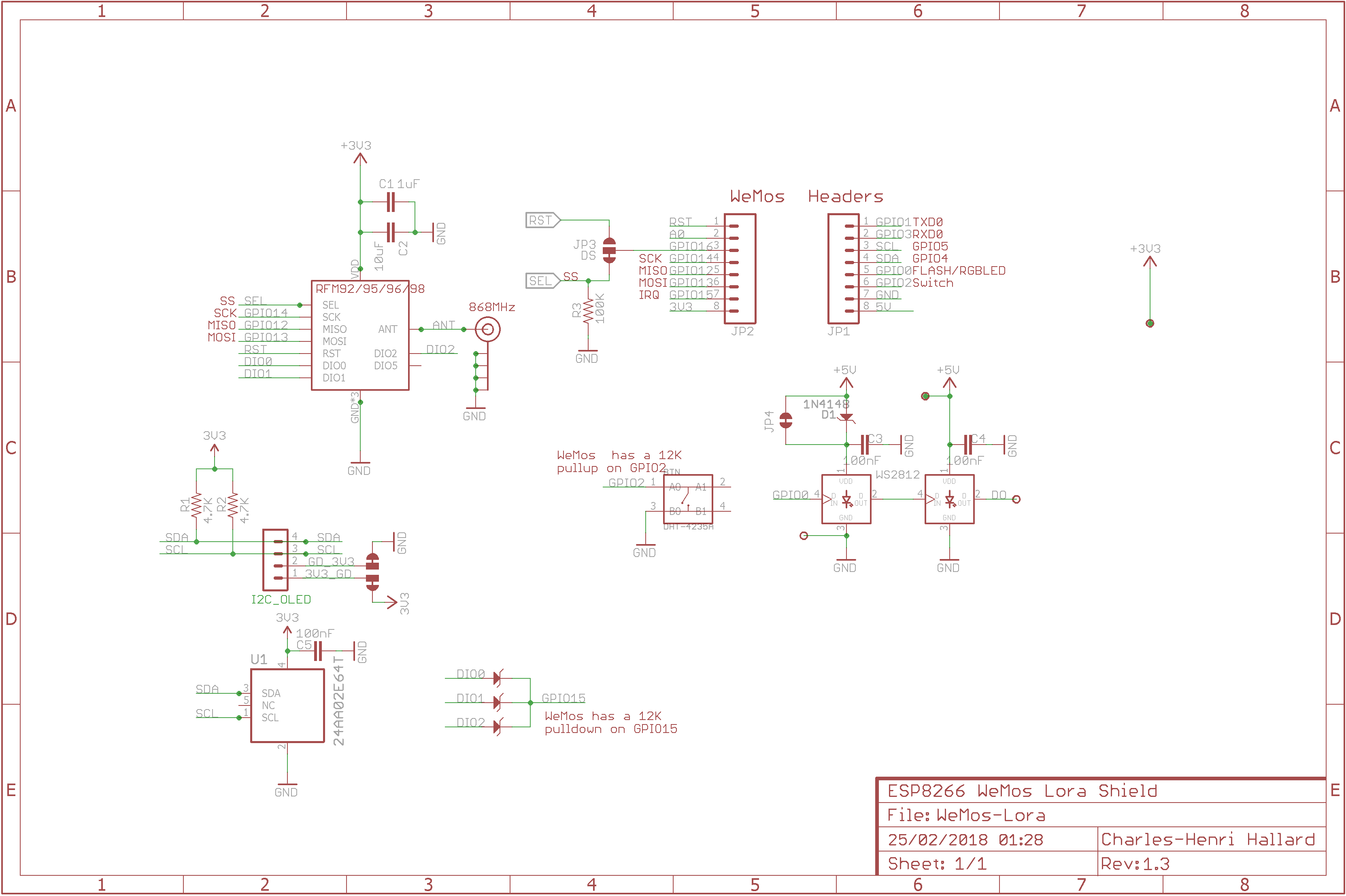
Anyway I think on my WeMos (and all others) I'll modifiy schematic as follow, it should works in all case
Then code would be based on this
const lmic_pinmap lmic_pins = {
.nss = 16,
.rxtx = LMIC_UNUSED_PIN,
.rst = LMIC_UNUSED_PIN,
.dio = { 15, LMIC_UNUSED_PIN, LMIC_UNUSED_PIN},
};
I'll test this soon and post results here
There is now a software fix described in #24 , no need to have DIO connected to CPU GPIO
I did some Logic Analyzing on the SPI and DIO0 / DIO1 signals. As you can see it has to be rising edge for the interrupt. The DIO1 picture is the same. After DIO0 is high, you can see the polling of the registers on the SPI channel (CS/NSS low)
thanks for taking time to show us @galagaking exactly what I needed to check !
const lmic_pinmap lmic_pins = { .nss = 4, .rxtx = LMIC_UNUSED_PIN, .rst = LMIC_UNUSED_PIN, .dio = {2, LMIC_UNUSED_PIN, LMIC_UNUSED_PIN}, };
won't work on Moteino Mega LORA: Sketch keeps rebooting with printing "Starting" endless. If one of DIO1 or DIO2 gets a pin assigned (doesn't matter if connected or not) sketch gets in queued state after multiple lines with "Starting" but won't get to EV_TXCOMPLETE. Will test tomorrow if there is a difference if the pins are connected -older "testing" works fine with all pins connected and defined