 maxbbraun
commented
2 years ago
maxbbraun
commented
2 years ago Very cool! Thank you for sharing.
Open jil24 opened 2 years ago
maxbbraun
commented
2 years ago Very cool! Thank you for sharing.
I initially had built this using the original plans, but found I could not reliably get the camera cable to bend enough to close the case without breaking the cable. Also, the original 3D geometry had extremely tight tolerances (hard to insert the camera board) and was very challenging to print on consumer grade mSLA resin printers like mine due to many unsupported overhangs. I also really wanted that nice pivot joint from the original iSight back. Starting from the original housing model, I modified the plans.
Changes
My Assembly Steps:
Strip iSight for casing and original status LED
Solder connection wires to LED, resistor, and Pi I/O pads #13
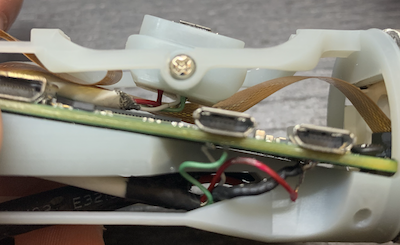
Solder connection wires to micro-usb plug and test points on Pi. These connections will be pretty fragile.
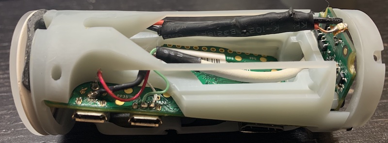
Mount board in housing, screw in. Add micro SD card. Bend wires to position LED. Route micro-usb wires and plug down into pivoting connector.
Snap in and screw down pivoting connector into main housing (M2x6mm screws):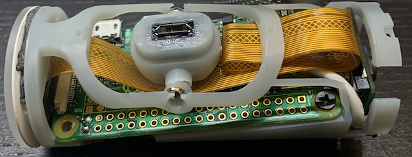
Mount camera board like in original plans
Mount and screw in the lens cap mounting ring (M2 screws). This is fragile, do not overtighten. If the screw caps protrude too far over to the outside or inside of the ring, sand/file them down to flush.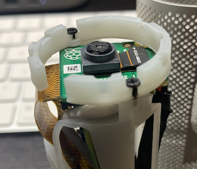
Connect up camera board and Pi, gently fold excess cable. You will still need to bend the cable close to the Pi end almost 90 degrees. It’s best to do this while bracing the contacts between pages of a book or something to avoid damaging the contact surfaces, which don’t like bending. Only bend it once if possible and have extra camera cables on hand because I went through 3 camera cables before I got this to work.
Test the camera, make sure everything works.
Slide assembled housing into case. Add lens cap/cover with very gentle wiggling. I was not able to get the rear cover to snap on, so I used double sided foam tape to hold it on.
Plug it in, wiggle the connector onto your choice of stand: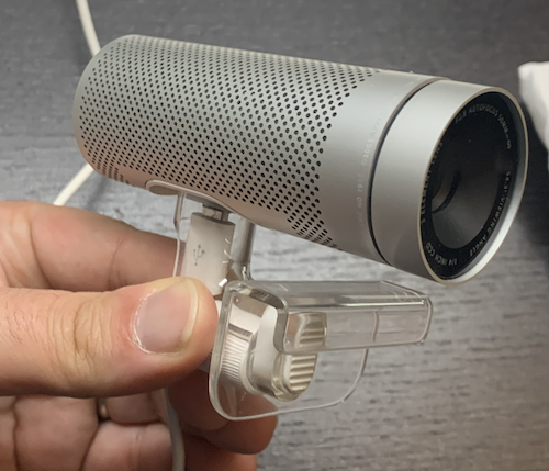
STL files for the main housing, the lens cap mount, and the pivoting connector are attached. STLs.zip I sourced the micro-usb female plug here: https://www.amazon.com/dp/B01A6M86YI