 itbetters
commented
6 years ago
itbetters
commented
6 years ago @akellai Thanks we are looking forward your schematic regards
Open ivoras opened 7 years ago
itbetters
commented
6 years ago @akellai Thanks we are looking forward your schematic regards
 akellai
commented
6 years ago
akellai
commented
6 years ago @itbetters, please take a look here https://github.com/akellai/rfid-music/blob/master/pinout.txt
itbetters
commented
6 years ago @akellai As I searched for Arduino pro mini regulators, I found these regulators on the 3.3v boards: KB33, S20K, F34V, L0RA, L0RB and the first one (KB33) is most popular .The quiescent current for it (mic5205) is about 150uA which doesn't seem ideal since I have found some other regulators with 70uA or less ! what is the regulator on your arduino board?
akellai
commented
6 years ago @itbetters, not sure but it reads "DE=A10". Could it be RT9193?
 octavio2895
commented
6 years ago
octavio2895
commented
6 years ago @akellai Hello, I've been reading this and I think I will use you code in the project I'm working on. I just want to mention one thing: battery energy is not linear to battery voltage.
That is, just because you battery dropped 10% of the initial voltage doesn't mean that the energy is 10% less than initial. In fact, most battery drop comparable amounts of voltage right at the start, that will explain the hockey stick figure you saw.
Heres a diagram from a simple Duracell Coppertop AA battery:

It's a bit tricky to interpret but this graph shows, in a way, the energy consumption of a battery. Energy = Power x Time and Power = Voltages x Amperage. Since the amperage is held constant for this curve, then you can imply that voltage is directly proportional to power AND voltage is directly related to energy for this graph. That means that the area under the curve equals the total energy capacity of the battery.
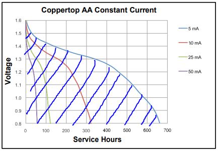
As you can note, the energy capacity is largely dependent on the current consumption of the device. To estimate the energy left in the battery by reading the voltage (note: the voltage should be operating voltage, not open circuit voltage) you can draw a line. Say the voltage of a single cell is 1.2v.

The area in red represents the energy already consumed by the load at that voltage and the area in green represents the energy left in the battery. Even though the voltage is 75% the nominal voltage, the area looks to be 20% of the total capacity.
If I use your example, you stated that you voltage is 4.27 or 1.42 per cell. Assuming you used a duracell coppertop my best guess is that you battery is somewhere between 70-80% of total capacity.
One last thing to note: depending on you cutoff voltage, the energy left within the battery could be useful. The built-in regulator, MIC5205, has a 17mV dropout which is next to nothing. However, that means that once the cell voltage approaches 1V or 3V in series, the energy left inside won't be used and is therefore wasted. Looking at the graph, I would say that that is about 5% leftover which is very good.
This means the the usable capacity left in your batteries is about 65-75%. Assuming power consumption stays the same, the total lifespan of you batteries should be ~620 days and should be running out by Christmas this year.
I'm sorry to intrude with this! I just hope this proves useful for future readers.
 Lotrax
commented
5 years ago
Lotrax
commented
5 years ago @akellai https://github.com/miguelbalboa/rfid/issues/269#issuecomment-292783655
This was exactly what I was looking for. Thank you so much. I was looking into how to get PICC_WakeupA working, but I haven't dived that deep into code before. This function does exactly what I needed it to do. However, I am using multiple RFID readers, so I've expanded on your code a little bit to make it work with multiple readers. See below.
#include <SPI.h>
#include <MFRC522.h>

#define RST_PIN         13          // Configurable, see typical pin layout above
#define SS_1_PIN        2         // Configurable, take a unused pin, only HIGH/LOW required, must be diffrent to SS 2
#define SS_2_PIN        3          // Configurable, take a unused pin, only HIGH/LOW required, must be diffrent to SS 1
#define SS_3_PIN        4
#define SS_4_PIN        5
#define SS_5_PIN        6
#define SS_6_PIN        7

#define NR_OF_READERS   6

byte ssPins[] = {SS_1_PIN, SS_2_PIN, SS_3_PIN, SS_4_PIN, SS_5_PIN, SS_6_PIN};

MFRC522 mfrc522[NR_OF_READERS];   // Create MFRC522 instance.

void setup() {
  Serial.begin(9600); // Initialize serial communications with the PC
  SPI.begin();        // Init SPI bus
  delay(500);

  for (uint8_t reader = 0; reader < NR_OF_READERS; reader++) {
    mfrc522[reader].PCD_Init(ssPins[reader], RST_PIN); // Init each MFRC522 card
    delay(100);
    Serial.print(F("Reader "));
    Serial.print(reader);
    Serial.print(F(": "));
    mfrc522[reader].PCD_DumpVersionToSerial();
  }
}

/**
   Main loop.
*/
void loop() {

  for (uint8_t reader = 0; reader < NR_OF_READERS; reader++) {

    mfrc522_fast_Reset(reader); // Sends along the value of the current reader.

    if (mfrc522[reader].PICC_IsNewCardPresent() && mfrc522[reader].PICC_ReadCardSerial()) {
      Serial.print(F("Reader "));
      Serial.print(reader);
      dump_byte_array(mfrc522[reader].uid.uidByte, mfrc522[reader].uid.size);
      Serial.println();

      mfrc522[reader].PICC_HaltA();
      mfrc522[reader].PCD_StopCrypto1();
    }
  }
}

void dump_byte_array(byte *buffer, byte bufferSize) {
  for (byte i = 0; i < bufferSize; i++) {
    Serial.print(buffer[i] < 0x10 ? " 0" : " ");
    Serial.print(buffer[i], HEX);
  }
}

// Function requires an integer assigned to specific reader, see for loop above.
void mfrc522_fast_Reset(int reader) {
  digitalWrite(RST_PIN, HIGH);
  mfrc522[reader].PCD_Reset();
  mfrc522[reader].PCD_WriteRegister(mfrc522[reader].TModeReg, 0x80);      // TAuto=1; timer starts automatically at the end of the transmission in all communication modes at all speeds
  mfrc522[reader].PCD_WriteRegister(mfrc522[reader].TPrescalerReg, 0x43);   // 10μs.
  //  mfrc522.PCD_WriteRegister(mfrc522.TPrescalerReg, 0x20);   // test

  mfrc522[reader].PCD_WriteRegister(mfrc522[reader].TReloadRegH, 0x00);   // Reload timer with 0x064 = 30, ie 0.3ms before timeout.
  mfrc522[reader].PCD_WriteRegister(mfrc522[reader].TReloadRegL, 0x1E);
  //mfrc522.PCD_WriteRegister(mfrc522.TReloadRegL, 0x1E);

  mfrc522[reader].PCD_WriteRegister(mfrc522[reader].TxASKReg, 0x40);    // Default 0x00. Force a 100 % ASK modulation independent of the ModGsPReg register setting
  mfrc522[reader].PCD_WriteRegister(mfrc522[reader].ModeReg, 0x3D);   // Default 0x3F. Set the preset value for the CRC coprocessor for the CalcCRC command to 0x6363 (ISO 14443-3 part 6.2.4)

  mfrc522[reader].PCD_AntennaOn();            // Enable the antenna driver pins TX1 and TX2 (they were disabled by the reset)
}
Do note: this code is a bit redundant in the way it's currently programmed. I could simply remove mfrc522[reader].PICC_HaltA(); and NOT use the void mfrc522_fast_Reset(), but that's not the point of me testing this. I want full control over which PICC to halt, to stay ready or to reset.
Again, thank you @akellai for sharing your code!
Also thanks to @octavio2895 for his addition to this discussion. This is indeed good information for anyone interested in doing any project working on batteries.
 Oegtsgeest
commented
3 years ago
Oegtsgeest
commented
3 years ago OS version: W10___
Arduino IDE version: 1.8.12
MFRC522 Library version: v1.4.8
Arduino device: SAMD21 adafruitfeather M0
MFRC522 device: RFID-RC522
Tried to save power by switching off and on when required. I used the code as given by akellai . And use the fasttrack(). It works as a stand alone sketch, however when I combine it with other software in which the I use different spi settings it does not work anymore. I suspect I have to use SPI.beginTransaction(SPISettings(MFRC522_SPICLOCK, MSBFIRST, SPI_MODE0)); and SPI.endTransactions. Where do I need to use those lines? Before and after each call to MRFC522.xxxx ?
Help is appreciated
 herm
commented
2 years ago
herm
commented
2 years ago I made an example how to use ESP32's deep sleep mode with MFRC522. I haven't done exact measurements yet, but a quick test shows you should be in the <100µA region with a 1s interval. That's good enough for my application.
/* This is an example that show how to use MFRC522 with ESP32's deep sleep mode efficiently.
 * In the deep sleep stub handler a quick check to see if a card is present is done (~1.5ms).
 * Only if there is a card the full wake up sequence is initiated.
 *
 * In this handler almost all hardware is still uninitialized. Therefore all functions and data
 * must be put into RTC RAM. That means you can't call any of the IDF or Arduino functions.
 * Only ROM functions and direct register accesses are available.
 * Therefore all hardware access functions had to be reimplemented. All functions intended to be
 * called in deep sleep stub got an "ds" prefix.
 *
 * ATTENTION: Don't call these functions from your normal application. Only core 0 can access
 * RTC fast RAM and normal arduino programms run on core 1.
 *
 * TODO: Hardware reset is unsupported at the moment.
 */

/******************* Configuration *****************/
#define DEBUG_PRINT_ENABLED 1
#define MFRC_CS 27
#define MFRC_SCK 12
#define MFRC_MOSI 4
#define MFRC_MISO 0
#define sleep_time_in_us 1000000ll

#include <Arduino.h>
#include <SPI.h>
#include <MFRC522.h>

#include "rom/rtc.h"
#include "soc/rtc_cntl_reg.h"

MFRC522 mfrc522 { MFRC_CS, UINT8_MAX };

#if DEBUG_PRINT_ENABLED
#include "soc/uart_reg.h"
static const char RTC_RODATA_ATTR debug_fmt_str[] = "---------> dbg: %d\n";
static const char RTC_RODATA_ATTR stub_fmt_str[] = "Deep sleep stub entered!\n";
static const char RTC_RODATA_ATTR wake_fmt_str[] = "Card detected. Waking up!\n";
static const char RTC_RODATA_ATTR sleep_fmt_str[] = "Sleeping again!\n";
#define DEBUG_PRINT ets_printf
#else
#define DEBUG_PRINT(...) do {} while (0)
#endif

/* Remember register offsets in RTC memory as esp32_gpioMux table is not available in deep sleep stub. */
uint32_t RTC_DATA_ATTR cs_reg = esp32_gpioMux[MFRC_CS].reg;
uint32_t RTC_DATA_ATTR sck_reg = esp32_gpioMux[MFRC_SCK].reg;
uint32_t RTC_DATA_ATTR mosi_reg = esp32_gpioMux[MFRC_MOSI].reg;

#define MFRC_REGISTER_READ_TIME 7 //us, used to calculate timeouts

static inline __attribute__((always_inline)) void dsGpioAsOutput(uint8_t pin, uint32_t reg_offset)
{
    GPIO.enable_w1ts = ((uint32_t) 1 << pin);
    ESP_REG(DR_REG_IO_MUX_BASE + reg_offset) = ((uint32_t) 2 << FUN_DRV_S) | FUN_IE | ((uint32_t) 2 << MCU_SEL_S);
}

static inline __attribute__((always_inline)) void dsDigitalWrite(uint8_t pin, bool value)
{
    if (value) {
        GPIO.out_w1ts = ((uint32_t) 1 << pin);
    } else {
        GPIO.out_w1tc = ((uint32_t) 1 << pin);
    }
}

static inline __attribute__((always_inline))    uint32_t dsDigitalRead(uint8_t pin)
{
    return (GPIO.in >> pin) & 0x1;
}

/* Hardware SPI is not initialized in deep sleep stub. */
uint8_t RTC_IRAM_ATTR dsSpiTransfer(uint8_t data)
{
    dsDigitalWrite(MFRC_SCK, 0);
    for (int i = 0; i < 8; i++) {
        dsDigitalWrite(MFRC_MOSI, data & 0x80);
        dsDigitalWrite(MFRC_SCK, 1);
        data <<= 1;
        data |= dsDigitalRead(MFRC_MISO);
        dsDigitalWrite(MFRC_SCK, 0);
    }
    return data;
}

uint8_t RTC_IRAM_ATTR dsPCD_ReadRegister(MFRC522::PCD_Register reg)
{
    dsDigitalWrite(MFRC_CS, 0);
    dsSpiTransfer(0x80 | reg);
    uint8_t result = dsSpiTransfer(0);
    dsDigitalWrite(MFRC_CS, 1);
    return result;
}

void RTC_IRAM_ATTR dsPCD_WriteRegister(MFRC522::PCD_Register reg, uint8_t value)
{
    dsDigitalWrite(MFRC_CS, 0);
    dsSpiTransfer(reg);
    dsSpiTransfer(value);
    dsDigitalWrite(MFRC_CS, 1);
}

bool RTC_IRAM_ATTR dsMFRC522_FastDetect()
{
    dsPCD_WriteRegister(MFRC522::CollReg, 0);
    dsPCD_WriteRegister(MFRC522::ComIrqReg, 0x7F);
    dsPCD_WriteRegister(MFRC522::FIFOLevelReg, 0x80);
    dsPCD_WriteRegister(MFRC522::FIFODataReg, MFRC522::PICC_CMD_REQA);
    dsPCD_WriteRegister(MFRC522::BitFramingReg, 7);
    dsPCD_WriteRegister(MFRC522::CommandReg, MFRC522::PCD_Transceive);
    dsPCD_WriteRegister(MFRC522::BitFramingReg, 0x80 | 7);
    // 50ms timeout. Much longer than required, but should not ever be used at all => does not matter.
    for (uint32_t timeout = 0; timeout < 50000 / MFRC_REGISTER_READ_TIME; timeout++) {
        uint8_t irq_flags = dsPCD_ReadRegister(MFRC522::ComIrqReg);
        if (irq_flags & 0x30) {
            // RxIrq || IdleIrq
            return true;
        }
        if (irq_flags & 0x01) {
            // TimeoutIrq
            return false;
        }
    }
    printf("Error\r\n");
    return false;
}

void RTC_IRAM_ATTR dsMFRC522_FastReset()
{
    dsGpioAsOutput(MFRC_CS, cs_reg);
    dsGpioAsOutput(MFRC_SCK, sck_reg);
    dsGpioAsOutput(MFRC_MOSI, mosi_reg);
    // TODO: Set hardreset pin
    // Reset & Wakeup
    dsPCD_WriteRegister(MFRC522::CommandReg, MFRC522::PCD_SoftReset);
    while ((dsPCD_ReadRegister(MFRC522::CommandReg) & (1 << 4))) {
        // ~ 200us wake up time from power down
    }

    // Init timer
    dsPCD_WriteRegister(MFRC522::TModeReg, 0x80); // TAuto=1; timer starts automatically at the end of the transmission in all communication modes at all speeds
    dsPCD_WriteRegister(MFRC522::TPrescalerReg, 67); // 13.56MHz / (2 * 67 + 1) = ~100kHz => 10μs
    dsPCD_WriteRegister(MFRC522::TReloadRegH, 0); // Reload timer with 30, ie 0.3ms before timeout.
    dsPCD_WriteRegister(MFRC522::TReloadRegL, 30);

    dsPCD_WriteRegister(MFRC522::TxASKReg, 0x40); // Default 0x00. Force a 100 % ASK modulation independent of the ModGsPReg register setting
    dsPCD_WriteRegister(MFRC522::ModeReg, 0x3D); // Default 0x3F. Set the preset value for the CRC coprocessor for the CalcCRC command to 0x6363 (ISO 14443-3 part 6.2.4)
    dsPCD_WriteRegister(MFRC522::TxControlReg, 0x83); // Antenna on
}

void RTC_IRAM_ATTR dsMFRC522_SoftPowerDown()
{
    dsPCD_WriteRegister(MFRC522::CommandReg, MFRC522::PCD_NoCmdChange | 0x10);
}

void RTC_IRAM_ATTR esp_wake_deep_sleep(void)
{
    DEBUG_PRINT(stub_fmt_str);
    dsMFRC522_FastReset();
    if (dsMFRC522_FastDetect()) {
        // Card detected => Wake up system
        DEBUG_PRINT(wake_fmt_str);
        esp_default_wake_deep_sleep();
        return;
    } else {
        // No card => go to sleep again
        dsMFRC522_SoftPowerDown();

        DEBUG_PRINT(sleep_fmt_str);
#if DEBUG_PRINT_ENABLED
        //Wait till uart buffer is empty
        while (REG_GET_FIELD(UART_STATUS_REG(0), UART_ST_UTX_OUT)) {

        }
#endif
        // https://gist.github.com/igrr/54f7fbe0513ac14e1aea3fd7fbecfeab with addition of setting new wake up time

        // Add a fixed time offset to the current wake up time
        uint64_t current_ticks = READ_PERI_REG(RTC_CNTL_SLP_TIMER0_REG) | (static_cast<uint64_t>(READ_PERI_REG(RTC_CNTL_SLP_TIMER1_REG)) << 32);
        // same as rtc_time_us_to_slowclk(sleep_time_in_us, esp_clk_slowclk_cal_get())
        uint64_t sleep_time_in_ticks = (sleep_time_in_us << 19) / REG_READ(RTC_SLOW_CLK_CAL_REG);
        uint64_t new_ticks = current_ticks + sleep_time_in_ticks;

        WRITE_PERI_REG(RTC_CNTL_SLP_TIMER0_REG, new_ticks & UINT32_MAX);
        WRITE_PERI_REG(RTC_CNTL_SLP_TIMER1_REG, new_ticks >> 32);

        // Set the pointer of the wake stub function.
        REG_WRITE(RTC_ENTRY_ADDR_REG, (uint32_t )&esp_wake_deep_sleep);
        // Go to sleep.
        CLEAR_PERI_REG_MASK(RTC_CNTL_STATE0_REG, RTC_CNTL_SLEEP_EN);
        SET_PERI_REG_MASK(RTC_CNTL_STATE0_REG, RTC_CNTL_SLEEP_EN);
        // A few CPU cycles may be necessary for the sleep to start...
        while (true) {
            ;
        }
        // never reaches here.
    }
}

void setup()
{
    Serial.begin(115200);
    printf("setup() started\n");
    if (rtc_get_reset_reason(0) == DEEPSLEEP_RESET) {
        printf("Found card\n");
        SPI.begin(MFRC_SCK, MFRC_MISO, MFRC_MOSI); //Enable hardware SPI
        // Demo only: Dump card data
        if (mfrc522.PICC_ReadCardSerial()) {
            mfrc522.PICC_DumpToSerial(&(mfrc522.uid));
        }
    } else {
        printf("No card present\n");
    }

    printf("Entering deep sleep\n");
    esp_deep_sleep(sleep_time_in_us);
}

void loop()
{

}
hemandk
commented
2 years ago
hemandk
commented
2 years ago I made an example how to use ESP32's deep sleep mode with MFRC522. I haven't done exact measurements yet, but a quick test shows you should be in the <100µA region with a 1s interval. That's good enough for my application.
So I want to give your code a go, but a bit insure on the wiring between the ESP32 D1 mini and the RC522. How can I see what GIOP pins you are using on the ESP32?
herm
commented
2 years ago Pin configuration is right at the beginning:
#define MFRC_CS 27
#define MFRC_SCK 12
#define MFRC_MOSI 4
#define MFRC_MISO 0
You should be able to use any pins you want.
hemandk
commented
2 years ago Pin configuration is right at the beginning:
#define MFRC_CS 27
#define MFRC_SCK 12
#define MFRC_MOSI 4
#define MFRC_MISO 0
You should be able to use any pins you want.
Thanks that helped.
A nother question. I seem to have some issue scanning some of my NFC/RFID tags when running this code. If I dont go into sleep mode i have no issues scanning the same cards. Is there something i can try an adjust to help with this issue?
Also I'm trying to implement ESP NOW to push out the ID tag to a server. Would it be appropriate to call all the ESP now initialization in the void setup() after the card is found?
 ZnRobotics
commented
2 years ago
ZnRobotics
commented
2 years ago Well I power down both mcu (328p) and the the rc522 exit low power when card is detected. Still running on 4xAA batteries 6 months so far its a electronic safe hack rfid unlock. Hardware race conditions can be tricky.
I interests build rfid door lock rc522+mcu (328p) you can share information.
 6000850
commented
2 years ago
6000850
commented
2 years ago Well, I was also reading it but I haven't noticed any useful difference between soft power-down and hard power-down. (?)
And going to hard power-down is quite easy, I just set the RST pin low. To wake it up I call MFRC522.PCD_Init() and it sets RST pin high. You can also find that in PCD_Init() there is 50 milliseconds delay for crystal startup. I modified it for myself to only 5 ms and it seems to work well in my case.
And generally, for battery operation, right now I'm testing the mode that ATmega328 asks MFRC522 if there is any PICC, if not then ATmega sets MFRC's RST pin low and goes to sleep for a second itself. After a second ATmega wakes up, sets RST pin high, asks MFRC and then it all go to sleep again... (Of course if there is a PICC present then it is more complicated.)
And to be woken for as short time as possible I also noticed that in library there is set 25 ms timeout in TReloadReg registers. You can find it in PCD_Init(). This timeout is used in PCD_CommunicateWithPICC(). I shortened it to 10 ms and it seems to work. But like the wakeup delay I don't know what the right minimum is.
Hi . How can I do a hard power down without connecting to a pin reset?
 jk987
commented
2 years ago
jk987
commented
2 years ago How can I do a hard power down without connecting to a pin reset?
According to this (chapter 8.6.1, page 33) I guess you can't: https://www.nxp.com/docs/en/data-sheet/MFRC522.pdf
Seems quite logical because how would you wake it up again?
ZnRobotics
commented
2 years ago thank you very much for your reply. interested in a few things:
 BenMemescape
commented
1 year ago
BenMemescape
commented
1 year ago Thanks so much to @herm for that ESP32 code. I had to make a couple of modifications to get it working for me, which may be of help to anyone else trying to use it:
Remove these lines:
uint32_t RTC_DATA_ATTR cs_reg = esp32_gpioMux[MFRC_CS].reg;
uint32_t RTC_DATA_ATTR sck_reg = esp32_gpioMux[MFRC_SCK].reg;
uint32_t RTC_DATA_ATTR mosi_reg = esp32_gpioMux[MFRC_MOSI].reg;
(gpioMux is obsolete in the current version of ESP32-IDF)
Replace these lines:
dsGpioAsOutput(MFRC_CS, cs_reg);
dsGpioAsOutput(MFRC_SCK, sck_reg);
dsGpioAsOutput(MFRC_MOSI, mosi_reg);
with
dsGpioAsOutput(MFRC_CS, GPIO_PIN_MUX_REG[MFRC_CS]);
dsGpioAsOutput(MFRC_SCK, GPIO_PIN_MUX_REG[MFRC_SCK]);
dsGpioAsOutput(MFRC_MOSI, GPIO_PIN_MUX_REG[MFRC_MOSI]);
(Unlike gpioMux, GPIO_PIN_MUX_REG is available from within the stub, so no need to make special RTC variables anymore.)
After the call to dsMFRC522_FastReset(); add
ets_delay_us(1000);This allows an extra millisecond for the card to get ready. Without this, like @hemandk I was finding that detection was very hit and miss, and when it did work the effective range was drastically reduced. After trying various things I had a hunch that everything was just happening a bit too quickly, and tried this extra delay, and it fixed it totally. 1000 was my first guess, and turned out to be right on the money: 500 and even 750 are not enough. But I only have one MFRC522 so I don't know if it will be the same with every reader, there might be some variation.
Using this method I'm measuring an average current of just a few mA, about an order of magnitude less than my best previous method!
 Barabba11
commented
1 year ago
Barabba11
commented
1 year ago I would take advance of this topic to ask your kind suggestion. My goal is to make something working as long the card is near the reader, I have some dubts: 1) Should the card be moved away (powered down) and then close it again (powered up) to receive from it the code? Or there is a way with this library to "polling" the card when I want? SUpposing the card is always touching reader. 2) Is it safe for the card to be powered on 24/7? Or evantually, does it has a limited number of "wake ups"? 3) I would consider to poll the card every 10 seconds, for example, considering the card keeps near the reader, does the hard reset keep low for 9 seconds and 1second not, allow the process correctly? (time power up compared the time the card is transmitting, etc. all wil be succesfull at first read attempt?) WHat you racomend me for this purpose? Thank you
 Tasshack
commented
11 months ago
Tasshack
commented
11 months ago I think consumption can be much lower if wakeup stub code works on the ULP coprocessor of the ESP32. I am going to try to convert the software spi code to ASM so that it can be run while device is sleeping and only wakes up if a card is detected. It is not much harder than reading i2c temperature sensors with the ULP but only downside is all connected pins must be RTC GPIO to be controlled via ULP.
 travisjayday
commented
9 months ago
travisjayday
commented
9 months ago Pro tip: Only turn on the antenna right before issuing the start request to save extra power:
...
  PCD_WriteRegister(PCD_Register::CommandReg, PCD_Command::PCD_Transceive);
  PCD_WriteRegister(PCD_Register::TxControlReg,   0x83);  // Antenna on
  PCD_WriteRegister(PCD_Register::BitFramingReg, 0x80 | 7);
...
Moosems
commented
7 months ago
Moosems
commented
7 months ago @Rotzbua This seemed like the most appropriate place to ask: I am running a small project off a 9v battery and would like to improve its lifespan. Currently it only lasts a few hours because its running items. Is there a way to run the reader on a low power mode only so that it detects an rfid tag and sends an interrupt so I can know when to turn everything else back on?
Moosems
commented
7 months ago And is there a way to have it do this with the arduino on low power mode?
 BenUniqcode
commented
7 months ago
BenUniqcode
commented
7 months ago @Rotzbua This seemed like the most appropriate place to ask: I am running a small project off a 9v battery and would like to improve its lifespan. Currently it only lasts a few hours because its running items. Is there a way to run the reader on a low power mode only so that it detects an rfid tag and sends an interrupt so I can know when to turn everything else back on?
No, sorry. The whole point of this thread is because the MFRC522 cannot do low power card detection and has no way of waking up the MCU when it does detect a card. Polling is the only answer. With an ESP32 you can do this from a deep sleep stub (see herm's code earlier in the thread, and my updates to it); I don't know if there's anything similar on Arduino, but Arduino are usually not a great choice for low power. ESPs are better, and STMs better still (but harder to use). There are other RFID readers that support LPCD properly and can wake the MCU when they detect a card.
 zfranco55
commented
6 months ago
zfranco55
commented
6 months ago Is it possible to run the code on a board (PN532) with I2C protocol? or it can work on a modified card like here: https://forum.arduino.cc/t/rc522-rfid-rc522-switching-spi-to-uart-interface-or-i2c-possible/425741
Hello!
Reading the MFRC522 data sheet, it seems like it supports several power-saving modes, including a "soft power-down" mode (http://www.nxp.com/documents/data_sheet/MFRC522.pdf). Is there a way to use this functionality from this RFID library?
Or, generally, for battery operation, could you document some best practices for saving power when using this library?
Thanks!