mjs513 / FreeIMU-Updates

IMU - FreeIMU Library Zero Drift, Altitude & LSM303 Heading Stability
MIT License
325 stars 159 forks source link

MPU6050 + HCM5883L + Arduino Nano (switched to Teensy 3.1) #7

Closed delphir-com closed 9 years ago

delphir-com commented 9 years ago

Hi guys! Nice discussion there. I`m working now on my own gimbal for panoramic photo shooting and decided to use sensors for excellent camera positioning. I have MPU6050, HMC5883L and Arduino Nano.. at first I thought that "sensor" part of my gimbal will be the easiest one as there are a plenty of samples in the internet, but once I started to work on it - I found this annoying yaw drift problem. So after a continuous googling I came to your github repo Mike and this thread :)

For now I have a very simple question: is it possible to upload your freeimu lib into an arduino nano without cutting the magnetometer code-part? the original freeimu lib easily fits into the Nano but it has a huge drift (sometimes even on pitch and roll). As I understand you have added a lot of optimisation/etc math algorithms to the lib which must help with Yaw, but this affected the size of the sketch :) Is there anything what can be shrinked from the lib wihout loosing it`s functionality for using with my hardware? For example you have mentioned about AHRS vs MARG algorithms and in my case looks like MARG will be better as I have a HMC5883L so in total with mpu6050 this will give 9DOF.. What else can be removed?

P.S. Thanks for your great job on FreeIMU lib, Mike. Without you it would be frozen in the 2012...

P.P.S. I`m also thinking now on buying Tennsy 3.1 for this proj to get rid of this memory problem, but I wanna be sure that I will not reach this Yaw problem again.. as before buying my current HW I have also checked the internet and found a lot of videos about "MPU6050 with FreeImu without Yaw drift" but nobody have mentioned that this is not the original FreeImu lib and that this changed one will require more memory :)

mariocannistra commented 9 years ago

Hi delphir-com. Just my 2 cents: I strongly encourage you to switch to Teensy 3.1 ... I was on Arduino Pro Micro and like you I've found and fought with the memory barrier (29K). Now I'm working on a customized version of freeIMU-updates with SD data logging and additional functions specific to my needs. I'm now at 52 K and more important at least for me, the update frequency of calculations on sensors' data is at least 5 times higher than with the previous micro. Bye, Mario PS: thanks again to Mike for his wonderful work on the library

delphir-com commented 9 years ago

Hi mariocannistra,

Now I will definitely buy it :) What sensors are you using in your proj? can you confirm that Yaw problem is solved (or veeeery small) in comparison to the original FreeImu lib compatible with Arduino?

mariocannistra commented 9 years ago

I'm using MPU9150 (that has 6050 inside) + MPL3115A2 for barometer / altimeter + GPS Receiver - LS20031 5Hz (66 Channel). Will probably upgrade to other sensors asap (probably https://www.tindie.com/products/onehorse/lsm9ds0-teensy-31-mini-shield/ since it does also fit well the Teensy 3.1 headers) I did not measure yet the Yaw drift since I've been busy merging the code in one sketch and solving other issues with the SD. I leave the answer on this to Mike because I know all the work he did with various changes and improvements. ...and I will certainly align the copy of freeimu-updates that i'm using merging his recent improvements :-)

mjs513 commented 9 years ago

Hi delphir-com

Think that Mario pretty much answered most of your questions regarding it fitting on the micro or even the uno. I have been looking at reducing the code by removing the "a" option in the arduino sketch and removing temperature compensation. The tests that I have been doing have been mostly without the compensation on and still getting good results. The other thing you can remove is the altitude complimentary filter and the heading calculations. You can put those in the processing sketch if you still need them. Either way would still recommend using the Teensy 3.1. Will give you provide you with better performance as well as the option for any expansion that your would like to do.

As for the question of yaw drift, it seems to be resolved to more than an exceptional level with the changes I made. I have not run stress tests using the Madgwick vs Mahoney algorithms but from what I have seen so far the issue seems to be resolved, especially if you move the board rapidly and lay it to rest. The issue seems to be with the gyros. That is also one reason I was looking at the zero motion detect algorithm to try and zero the gyros automatically but still tinkering with that option. Remember there will always be some drifting if you go through the literature but so far it is quite good. Check some of the videos on YouTube under the CyberMerln channel. That shows some of the results to date. You can also check the wiki that I started to put together on the FreeIMU library.

Mike

PS. Thanks for compliments on the library updates.

delphir-com commented 9 years ago

I`m already keeping Teensy in my hands :) Will do my tests during the weekend and will let you know the results :)

delphir-com commented 9 years ago

For some reason the Arduino IDE swears about type conversions while I`m trying to compile FreeIMU_serial.

It is stated in FreeIMU readme, that 1.5.x IDE must be used, but Teensyduino is supported only by 1.0.x ide.. And I get these errors in 1.0.x..

Any suggestions?

FreeIMU_serial.ino: In function 'void loop()':
FreeIMU_serial:148: error: no matching function for call to 'MPU60X0::getMotion6(int*, int*, int*, int*, int*, int*)'
FreeIMU_serial.ino:148:135: note: candidate is:
In file included from FreeIMU_serial.ino:17:0:
C:\...<cut>...\libraries\MPU60X0/MPU60X0.h:605:14: note: void MPU60X0::getMotion6(int16_t*, int16_t*, int16_t*, int16_t*, int16_t*, int16_t*)
C:\...<cut>...\MPU60X0/MPU60X0.h:605:14: note:   no known conversion for argument 1 from 'int*' to 'int16_t* {aka short int*}'
FreeIMU_serial:151: error: no matching function for call to 'MPU60X0::getMotion6(int*, int*, int*, int*, int*, int*)'
FreeIMU_serial.ino:151:135: note: candidate is:
In file included from FreeIMU_serial.ino:17:0:
C:\...<cut>...\libraries\MPU60X0/MPU60X0.h:605:14: note: void MPU60X0::getMotion6(int16_t*, int16_t*, int16_t*, int16_t*, int16_t*, int16_t*)
C:\...<cut>...\libraries\MPU60X0/MPU60X0.h:605:14: note:   no known conversion for argument 1 from 'int*' to 'int16_t* {aka short int*}'
mjs513 commented 9 years ago

Hi delphir

I am using 1.05r2 with teensduino. If you take a look at the teensyduino download page it has the following warning:

A release candidate for next version of Teensyduino is available, with support for Arduino 1.0.6. Teensyduino 1.19 supports only Arduino version 1.0.5. Arduino 1.5.x BETA versions are not yet supported. Multiple copies of the Arduino software can coexist and even run simultaneously on the same computer.

but more to the point try running the FreeIMU_serial_ARM_cpu.ino instead of the FreeIMU_serial.ino on the teensy.

delphir-com commented 9 years ago

Finally I got it working with my new Teensy 3.1 board! :)

Some things I have noticed till this moment:

File "D:\Arduino\FreeIMU-Updates-master\FreeIMU-Updates-master\FreeIMU_GUI\FreeIMU_GUI\cal_lib.py", line 30, in calibrate
    H = numpy.array([x, y, z, -y**2, -z**2, numpy.ones([len(x), 1])])
ValueError: could not broadcast input array from shape (61300,1) into shape (61300)

Thats all for now :)

For those who will find this thread with same questions like I had I will leave a small comment here:

The "FreeIMU Updates" library works much better than the original Fabio`s "FreeIMU" library. 
The "Yaw Oscilation" effect (or like some people name it a "Yaw drift") still present in current 
release (don`t know how to name current version) but it is not more than 0.30 deg. in max
(it was hundreds of deg. in the original lib), 

so I would say that results are veeery good and will be Ok for most purposes!

UPD: heh 0.30 deg. was too optimistic. 5 to 10 degree in real. but still not bad.

P.S. Thank you Mike once again for your work. I will stay with you and will try to help getting library better! :)

mjs513 commented 9 years ago

Glad you got your Teensy 3.1 working. Will look at the change you suggested and will add the scipy package as well. Putting in the additional links will have to wait awhile. Getting ready to push some additional changes to the library to make it easier to change some of the settings on the accelerometers, gyros and magnetometer so it will match the wiki page.

Also, did you try both algorithms (MARG=0 gives you the MahoneyAHRS and MARG=1 gives you the MadgwickAHRS algorithm). One of the things I noticed is that besides have to make sure you do a good calibration is that various boards, even with the same chip configs, may need additional tuning of the Kp/Ki or the Beta terms. Also, remember to send the sketch a "g" command to zero out the gyros properly. If you are using the Processing sketch in the library then when select 0 for temp compensation it will do it automatically for you. Also, do not set the temp calib to 1 as the loaded cal is not for your board.

As for your note on the 5 to 10 degrees doesn't sound right you may need do some additional tuning I was seeing better numbers than that. To me 5 to 10 degrees is not acceptable +/- 0.3 is closer. Try running with MARG set to 0 (it's in the FreeIMU.h file). I will probably do more comparisons on the both the drift and the oscillatory nature (noticed this only with MARG=1 and dependent on the board) as soon as I get the wiki finished.

By the way what board are you using (know whats on it) its it a GY-xxx?

Mike

delphir-com commented 9 years ago

GY-521 + HMC5883L

http://www.ebay.com/itm/201002005334
http://www.ebay.com/itm/400495492540

Yea, I know re calibration, but have not tested MARG config yet. 5-10 oscillation not always appear, but only sometimes (right after the movement). And once I have changed serial speed to 115200 it became much smaller.

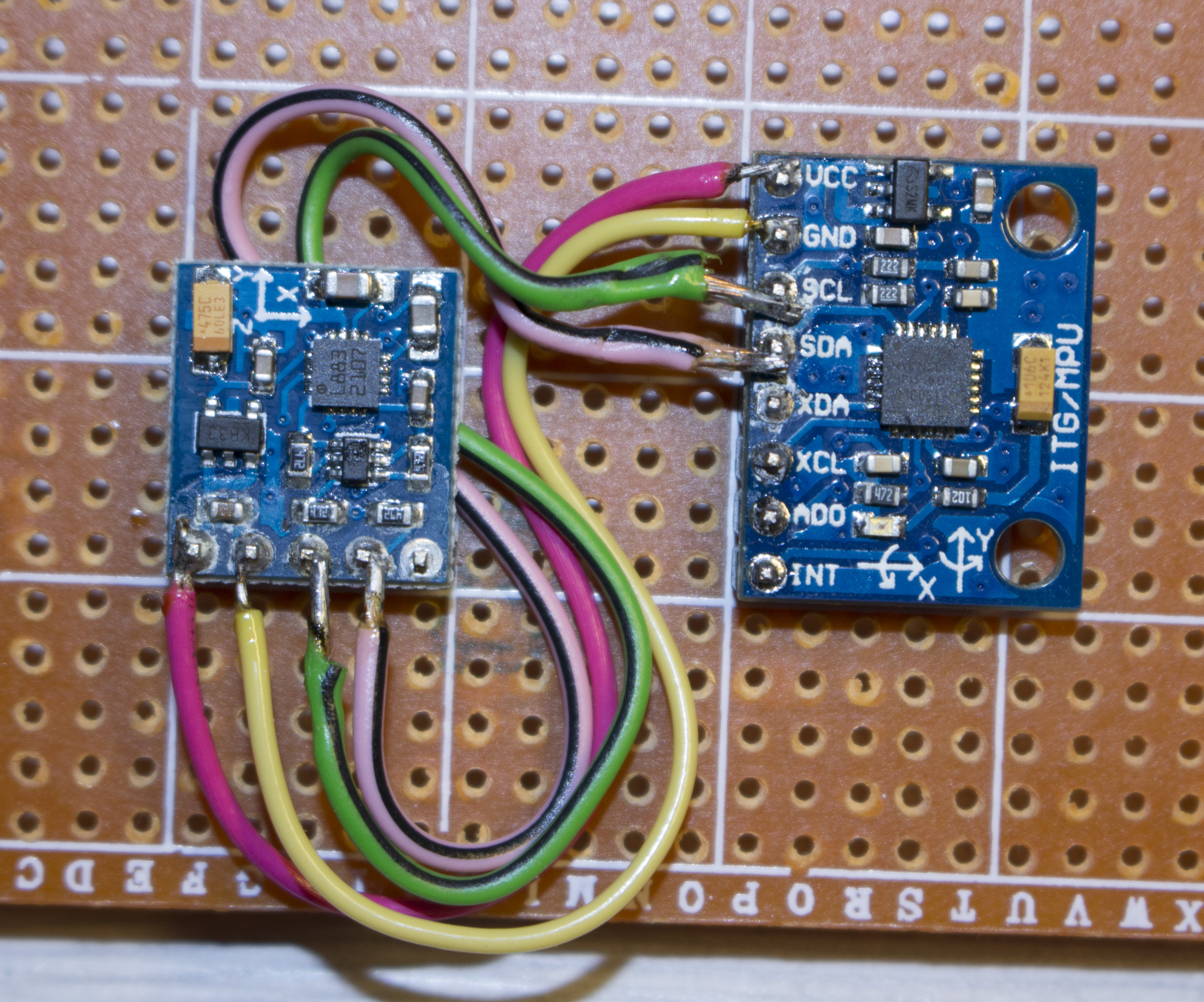
Btw. How can I set a "rotation" for one of the sensors? I wanna put them together one on another, so the accgyro X will be same as magn Y axe and accgyro Y will be same as magn.(-)X axe.. "Z" will stay the same.

I already tried to do this rotation in HMC58X3.cpp, but it is not working (during a calibration - magnetometer values are drawn in a single plane), if I remove the "-1" multiplication - then values are drawn in spherical view.

*y = (int16_t)(-1 * (int16_t)( (Wire.read() << 8) | Wire.read() ));
*z = (int16_t)((Wire.read() << 8) | Wire.read());
*x = (int16_t)((Wire.read() << 8) | Wire.read());
mjs513 commented 9 years ago

Actually, the reason why I asked about your board configuration is that both algorithms assume that the you have aligned your axes properly. That's also why in FreeIMU sketch it asks you if your board has your axis aligned and if its 9dof. You are actually going to have to add a new board the library. The next section of the wiki I was going to put up was how to do that. To be hones never test a two board config but seb madgwick did.

The lines of code that do the alignment are in the FreeIMU.cpp file - don't mess with other libraries, here are the specific lines:

if IS_9DOM() && not defined(DISABLE_MAGN)

if MARG == 0

    #if HAS_AXIS_ALIGNED()  
        AHRSupdate(val[3] \* M_PI/180, val[4] \* M_PI/180, val[5] \* M_PI/180, val[0], val[1], val[2], val[6], val[7], val[8]);
        //val[9] = maghead.iheading(0, 1, 0, val[0], val[1], val[2], val[7], val[6], val[8]);
        val[9] = calcMagHeading( q0,  q1,  q2,  q3, val[6], val[7], val[8]);
    #elif defined(SEN_10724)
        AHRSupdate(val[3] \* M_PI/180, val[4] \* M_PI/180, val[5] \* M_PI/180, val[0], val[1], val[2], val[7], -val[6], val[8]);
        val[9] = calcMagHeading( q0,  q1,  q2,  q3, val[7], -val[6], val[8]);
    #elif defined(ARDUIMU_v3)
        AHRSupdate(val[3] \* M_PI/180, val[4] \* M_PI/180, val[5] \* M_PI/180, val[0], val[1], val[2], -val[6], -val[7], val[8]);
        val[9] = calcMagHeading( q0,  q1,  q2,  q3, -val[6], -val[7], val[8]);  
    #elif defined(GEN_MPU9150) || defined(MPU9250_5611) || defined(GEN_MPU9250)
        AHRSupdate(val[3] \* M_PI/180, val[4] \* M_PI/180, val[5] \* M_PI/180, val[0], val[1], val[2], val[7], val[6], -val[8]);
        val[9] = calcMagHeading( q0,  q1,  q2, q3, val[7], val[6], val[8]); 
        //val[9] = maghead.iheading(1, 0, 0, val[0], val[1], val[2], val[7], val[6], -val[8]);
    #endif
#endif
#if MARG == 1
    #if HAS_AXIS_ALIGNED()      
        MadgwickAHRSupdate(val[3] * M_PI/180, val[4] * M_PI/180, val[5] * M_PI/180, val[0], val[1], val[2], val[6], val[7], val[8]);
        //val[9] = maghead.iheading(0, 1, 0, val[0], val[1], val[2], val[7], val[6], val[8]);
        val[9] = calcMagHeading( q0,  q1,  q2,  q3, val[6], val[7], val[8]);
    #elif defined(SEN_10724)
        MadgwickAHRSupdate(val[3] * M_PI/180, val[4] * M_PI/180, val[5] * M_PI/180, val[0], val[1], val[2], val[7], -val[6], val[8]);
        val[9] = calcMagHeading( q0,  q1,  q2,  q3, val[7], -val[6], val[8]);
    #elif defined(ARDUIMU_v3)
        MadgwickAHRSupdate(val[3] * M_PI/180, val[4] * M_PI/180, val[5] * M_PI/180, val[0], val[1], val[2], -val[6], -val[7], val[8]);
        val[9] = calcMagHeading( q0,  q1,  q2,  q3, -val[6], -val[7], val[8]);    
    #elif defined(GEN_MPU9150) || defined(MPU9250_5611) || defined(GEN_MPU9250)
        MadgwickAHRSupdate(val[3] * M_PI/180, val[4] * M_PI/180, val[5] * M_PI/180, val[0], val[1], val[2], val[7], val[6], -val[8]);
        val[9] = calcMagHeading( q0,  q1,  q2, q3, val[7], val[6], val[8]); 
        //val[9] = maghead.iheading(1, 0, 0, val[0], val[1], val[2], val[7], val[6], -val[8]);
    #endif
#endif

As a FYI, first 3 vals are the gyros, second 3 are the accels, and the last 3 are the magnetometer axis. Take a look at the image

axis alignment

Some of your drifting may be due to misconfiguration as well as the board warming up. PS with the MPU6050 once you connect it don't move it right away, let it sit for a minute - has to do with its warm up process. Also keep in mind the other things I mentioned.

Good luck. if you need help send me a good closeup image of your setup - give it a try first - you will learn more. By the way you pretty much have to do this with all the other methods out there as well. One of the things on the to do list was to see if I could simply this but I don't think so.

Mike

delphir-com commented 9 years ago

Yeah, I have added my own board config which is close to the Freeimu v4 but without a pressure sensor and I set it as 9dof. Everything what I wrote before this was tested with both sensors propertly aligned, simply I'm trying to modify their alignment now to make pcb a little bit compact :) Thanks for the reminder re MPU6050 usage but I know them all, so this is not a reason for oscillation.

mjs513 commented 9 years ago

Ok. There were two things you brought up in your previous post, one was on where you change your axes configuration and the other was a discussion on the jitter or oscillation you are seeing. Gave you the answer on where you make the axes alignment modifications - assumed that that were not aligned before.

If you look at a video of that Seb Madgwick posted on YouTube you will see the same oscillation when at rest. Saw another video using that some else posted and it was there as well. You will have to tune the beta term to reduce the jitter - that's what I did for all the boards - each board you will probably have to re-tune. Why you are seeing that magnitude jitter sometimes I can only guess. Like I said I am still experimenting with that version. Like I said earlier try using the MahoneyAHRS algorithm - MARG=0. You may still have to tweak Kp/Ki since you are not really using FreeIMU v4 board. Did notice that the quality of the boards do matter.

delphir-com commented 9 years ago

Not succeed with MARG=0. it is too hard to understand how to get correct values for Kp/Ki without reading additional documents and had no time for that yet (btw, if this must be done with some "logic" - then why not to add these values calibration into the GUI and just let the UI to do this calibration in auto mode ?)

But I have another question now (MARG=1). Here are the graphs of the values which I get by printing the "ypr", "val" and "raw_values" arrays from the serial sketch. Graphs are starting just a second or so later after the sensors power reset (it was warmed before this and I just use a power reset to restart it, but for some reason temperature graph is still changing).

The question: why do we need these first 20-30 seconds period to get the correct values if the input sensor values are constant during this period? What I really cant understand is how the constant input values may change the output ypr values? is it some internal calculation used during this time? Or it is because Im currently not using temperature calibration?

Another question: Please look at the graps "19579" time(measure) moment. It is clearly seen, that right after the sensors stress YAW needs some time to get back to the correct position (sensors are not moved after 19579 moment). This is a yaw value change from 69 to 74 degrees. Is it because of the temperature drop during the stress time and then while the temp is comming back - YAW value is also returned?

image image image image image image

delphir-com commented 9 years ago

Less stressed test (rotations only around Z-axis on the table):

Yaw increased from 92.8 to 97.6 deg (16741-19066 moments) (placed back exactly into the same position and no movements during this period). Please note that graph`s min/max are different from the prev measurements.

image image image image image

mjs513 commented 9 years ago

Ok lets go in order of questions since there is a lot here:

  1. MARG=0. it is too hard to understand how to get correct values for Kp/Ki without reading additional documents....: Actually not really that hard, its in the wiki but repeated here - Seb Madgwick in 2011 he suggested the following for tuning Kp and Ki:" Leave Ki as 0 and start with a Kp value of 5. You will want to reduce your Kp value from this by 10 or even 100 times when tuning. The lowest value of Kp you can use is dependent on: gyroscope bias calibration errors, and gyroscope sensitivity calibration errors and expected angular dynamics of application (coupled characteristics)." Check the code, Surprised you didn't ask about beta. Either way those factors control how fast the algorithm will converge, etc - read up on PID controllers. Something similar. Nope - can't be calculated in the GUI.
  2. Think you are seeing the algorithm starting up and converging - right now it starts from quaternions of (0,0,0,1) which is really the best start up. Working on that one when I have time. Not hard to do.
  3. The ypr values are calculated from the quaternions coming out of the algorithm not directly from the sensor values So as the quats change so does YPR.

4, Yep the CPU temp profile changes from idle to full load and then cools down and goes back up - at least for the MPU-6050 I have seen that.

  1. In looking at the data I did notice that the mag values didn't return to the same values as before you started your movement so it is possible that you might be off a few degrees when you return to starting point - believe me its real easy to be. Also noticed that the pitch angle is different by a little bit as well (noticed this in the second set of charts). I usually align the headings to be the same and check see if everything goes back to where it was before.
  2. Chart set 1 - it looks like your movement starts at about 17069 and about mid-way between 19077 and 19577 (this is based on the sensor data) and coming back to pretty close to starting position by 20500 (note that this is a difference of 1000 moments in time - but if you look closely it within what a .1 deg or less at 19579 or so).
delphir-com commented 9 years ago

I`m playing now with "beta" initial value and beta adjustments back to 0.1f during the first calibration to force values to became stable faster.

That`s what I have so far: image

Yaw value at the moment 75 is 153.41 deg. At 700 = 156.04 At 2110 = 156.70 <- this one is stable and will not change a lot after that (will just jump around this value a little).

In comparison to my previous graphs - such difference in values was started only after 3000`s moments when compared to 3200's stable). I will post the total idea description once I will be sure that I'm on the 100% right way.

re Ki/Kp adjustments: "You will want to reduce your Kp value from this by 10 or even 100 times when tuning." -- this one is too complex :) If this one must be selected with some "logic" then we can try to put this logic into GUI to help user make a decision on the right values :)

mjs513 commented 9 years ago

Just out of curiosity - what beta are u using. Stop play tweaking for now while I am checking all Imus I have with the Teensy. Finding a few minor things that have to fixed. On Oct 5, 2014 5:05 PM, "delphir-com" notifications@github.com wrote:

I`m playing now with "beta" initial value and beta adjustments during the first calibration to force values to became stable faster.

That`s what I have so far: [image: image] https://cloud.githubusercontent.com/assets/7754573/4519935/31e072ee-4cd2-11e4-8b0a-8914fd7f540c.png

Yaw value at the moment 75 is 153.41 deg. At 700 = 156.04 At 2110 = 156.70 <- this one is stable and will not change a lot after that (will just jump around this value a little).

In comparison to my previous graphs - such difference in values was started only after 3000`s moments. I will post the total idea description once I will be sure that I'm on the 100% right way.

re Ki/Kp adjustments: "You will want to reduce your Kp value from this by 10 or even 100 times when tuning." -- this one is too complex :) If this one must be selected with some "logic" then we can try to put this logic into GUI to help user make a decision on the right values :)

— Reply to this email directly or view it on GitHub https://github.com/mjs513/FreeIMU-Updates/issues/7#issuecomment-57952288 .

delphir-com commented 9 years ago

I`m starting with value of 358 and going down to 0.1f giving it a time to get stable.

Here is my very first graph (posted a day ago) but with the same measurements count as in the last one, so you can see the difference:

image

delphir-com commented 9 years ago

okay, I think you may try to repeat my tests and if you will be satisfied then you can reuse my code:

here is a comparison result for the sensor sticked to the table (betaDef = 0.3f): image

I used these simple code to "tune" beta during the start period:

#define betaDefInit  358.0f

    if ( beta > betaDef ){
        betaStartStep++;

        if ( betaStartStep % 7 == 0 ){
            //
            beta = beta * ( 0.7 );
            if ( beta < betaDef ){
                beta = betaDef;
            }
        }
    }

I have added it to the "getYawPitchRollRad()" function but this definitely must have some another place to be available for getting same result from GUI (as I understood this method is not called when connected with GUI, but serial output is Ok for me).

mjs513 commented 9 years ago

If I understand what you are doing is to visually compare the results of the changing beta automatically via code and determining the best value? If now how to settle on a correct value. If you read the paper the Beta term is way less than one and from what I am seeing a good starting point is around 2 and lower. Here is a quote by Seb Madgwick regarding beta based on the method in his original paper:

sebmadgwick wrote: khatarat wrote:...possible explain more about this two variables and also beta and zeta.

I will summarise the algorithm and explain beta’s role:

The filter uses a quaternion to represent orientation. Gyroscope data is represented as the rate of change of a quaternion which, when integrated, provides the estimated orientation of the sensor array. However, this estimate alone will drift over time and so must be ‘corrected’.

The accelerometer and magnetometer provide measurements of the earth’s gravitational and magnetic fields (respectively) which may be compared to the expected measurements of each field (according to the estimated orientation of the sensor array) to compute an error. Using non-linear programming methods, this error can be used to compute a vector in quaternion space that defines the required ‘corrective step’ that must be taken to reduce the error in the quaternion describing the estimated orientation . If this vector is normalised to a unit vector then it may be multiplied by a gain (beta) that defines the rate of ‘correction’ or the ‘rate of convergence’.

If the rate of convergence (beta) is too great then the filter output will be ‘noisy’ as it tries to track all accelerometer and magnetometer data; but if the rate of convergence is too small integral drift may take hold. Therefore an optimal value of beta may be defined as that which ensures the rate of convergence due to the ‘corrective step’ is equal to the rate of divergence due to integral drift. The divergence due to integral drift is the the gyroscope measurement error (gyroMeasError). The units of beta are defined as the ‘magnitude of the rate of change of quaternion’, the units of gyroMeasError are degrees per second; therefore a simple conversion is required (section 3.6 of report).

khatarat wrote:... can i use values in your program?

I recommend using zeta=0 initially on the condition that you observe gyroscope bias drift as being negligible. Once you have a beta value that provides suitable convergences, then tune a zeta value to suitable tackle your gyroscope bias drift.

zeta is related to paper ( see his paper) which also has this in the header for his code: // System constants

define deltat 0.001f        // sampling period in seconds (shown as 1 ms)

define gyroMeasError 3.14159265358979 * (5.0f / 180.0f)         // gyroscope measurement error in rad/s (shown as 5 deg/s)

define gyroMeasDrift 3.14159265358979 * (0.2f / 180.0f)           // gyroscope measurement error in rad/s/s (shown as 0.2f deg/s/s)

define beta sqrt(3.0f / 4.0f) * gyroMeasError                                  // compute beta

define zeta sqrt(3.0f / 4.0f) * gyroMeasDrift                                    // compute zeta

this puts beta around 0.08 for a 5deg measurement error. If you use what he wrote you might be able to figure beta automaticallay after a few minute run so you are definitely on the right track. Keep me posted on what you are doing.

Thanks for your help - you are giving me a myriad of ideas and making me dig into the Beta term. By the way if I didn't say it before great work on your analysis, I tend to get caught up in the details sometimes.

Mike

delphir-com commented 9 years ago

re your answer: I have not read paper describing Beta before, but what you wrote +/- is the same how I understood it`s requirement in the code. So I'm using a beta value to "quickly" figure out the correct stabilized value (in your term - I'm trying to use a higher bet again to use a bigger "step" for faster stabilization). Even if the higher beta values provide a bigger noise - all this noise is "around" the final value, so a few starting steps with a high noise (but bigger steps) allows us to get closer to the final values... and with every next N-th step (in my sample every 7-th) we are decreasing beta to lower the noise and get closer and closer to final values again and again.


Unrelated to your reply: I just noticed an interesting bug(?). When the sensors are placed with "X" axis facing up (Z and Y are flat on the table) - Yaw value cannot be stabilized and is always flying from -90 to +90 (more time spending around -90)

image

Maybe I have placed boards wrongly in relation one to another? I'm using the default sensor alignment for this last test (MARG=1):

        #if HAS_AXIS_ALIGNED()      
            MadgwickAHRSupdate(val[3] * M_PI/180, val[4] * M_PI/180, val[5] * M_PI/180, val[0], val[1], val[2], val[6], val[7], val[8]);
            val[9] = calcMagHeading( q0,  q1,  q2,  q3, val[6], val[7], val[8]);

image

P.S. graph values are made with beta=0.1 and with your original (unchanged) sketch code. When sensors ace placed with X and Y flat on the table - values quickly stabilizes as on my prev graphs.

mjs513 commented 9 years ago

Doesn't really matter where you start just pointing out if you want to save time you can start from a lower value but my question still stands - what's your criteria for know when you have a good beta that can be implemented in the code without looking at the multiple charts.

As to your other question - your setup looks aligned (I checked not only the silk screening but also the sensor pinout, I am assuming you also have 9dof selected as well. All I can say is that I have not seen what you show but then i never plotted it. Just remember when you go past 90 will change sign and point from north to south since yaw is measured from north. I just checked with the 9250 board that I currently have setup. I will check later with the FreeIMU board.

delphir-com commented 9 years ago

If I will start with a lower value - then "noise" will faster move average to the correct value range (as sometimes we need several steps to reach this range). I`m not checking exit values at all, I just know that several steps at every level (beta value) will allow algorithm to reach the necessary value.

Re my question re Yaw jumping from -90 to +90: Yes, I`m using "9dof". In this example sensors were stable fixed on the table with X-axe pointing up.

mjs513 commented 9 years ago

Ok - had to ask on the 9Dof. I will give it a try with FreeIMU board as soon as I get a chance

mjs513 commented 9 years ago

delphir

Wondering if you can verify something for me. Can you replace the axis aligned code for the Marg=1 (since that is what you are working with) and see if you get better results:

        MadgwickAHRSupdate(val[3] * M_PI/180, -val[4] * M_PI/180,-val[5] * M_PI/180, val[0], -val[1], -val[2], val[6], -val[7], -val[8]);
        val[9] = calcMagHeading( q0,  q1,  q2,  q3, val[6], -val[7], -val[8]);

Reason: FreeIMU assumes that +Z points down - if your board points down axes are shifted and have to follow the right hand rule so its a rotation about the x-axis for the values.

thanks Mike

delphir-com commented 9 years ago

X pointing down: image

X pointing up: image

X and Y flat on the table: image

[original code] X and Y flat on the table: image

[original code] X pointing up: image

mjs513 commented 9 years ago

Ok - now you got me. I am going to try an repeat your results with the FreeIMU board. Can you tell me where you are pulling the data for your charts from, i.e, from the Processing sketch, Arduino sketch? Also, think you said you are using 0.03 for beta. I am at work now so probably won't get to it until tonight or tomorrow. Because to be honest I am not seeing what you are seeing when I duplicate your actions (from just looking at it through the GUI.)

By the way I am making a few changes to the FreeIMU.h and FreeIMU.cpp file that I will push tonight - increases the sample rate of the accel.

Have to ask - because I did it myself and was wondering why the mag was acting funny - are you rotating the board on a table that has iron legs which is different than where you ran your calibration? What's mag by the way (heading?). Also, what does your accel, gyro and magnetometer readings look like when you rotate the board?

thanks Mike

On Thu, Oct 9, 2014 at 10:31 AM, delphir-com notifications@github.com wrote:

X pointing down: [image: image] https://cloud.githubusercontent.com/assets/7754573/4577603/e734bb94-4fbd-11e4-8e20-ff4e85039bd8.png

X pointing up: [image: image] https://cloud.githubusercontent.com/assets/7754573/4577680/9a56ceba-4fbe-11e4-8959-16e8c85effcc.png

X and Y flat on the table: [image: image] https://cloud.githubusercontent.com/assets/7754573/4577746/26555a8a-4fbf-11e4-957c-458c328bad75.png

[original code] X and Y flat on the table: [image: image] https://cloud.githubusercontent.com/assets/7754573/4577857/40ffebd8-4fc0-11e4-9568-76efe825a6e8.png

[original code] X pointing up: [image: image] https://cloud.githubusercontent.com/assets/7754573/4577946/de204c78-4fc0-11e4-8184-2231d330df5b.png

— Reply to this email directly or view it on GitHub https://github.com/mjs513/FreeIMU-Updates/issues/7#issuecomment-58517897 .

delphir-com commented 9 years ago

I'm printing data from the

else if(cmd == 'd') { // debugging outputs
}

block in the sketch through the serial output.

I also upgraded this section to auto-reset all calibrations on start to get the same starting point on every run

    else if(cmd == 'd') { // debugging outputs

      float qVal = 0.125; //Set Q Kalman Filter(process noise) value between 0 and 1
      float rVal = 32.; //Set K Kalman Filter (sensor noise)

      for(int i = 0; i <= k_index; i++) { //Initialize Kalman Filters for 10 neighbors
      //KalmanFilter(float q, float r, float p, float intial_value);
        kFilters[i].KalmanInit(qVal,rVal,5.0,0.5);
      }

      my3IMU.init(true);

      while(1) {
        my3IMU.getRawValues(raw_values);
        sprintf(str, "%d %d %d %d %d %d %d %d %d %d %d ", raw_values[0], raw_values[1], raw_values[2], raw_values[3], raw_values[4], raw_values[5], raw_values[6], raw_values[7], raw_values[8], raw_values[9], raw_values[10]);

        my3IMU.getQ(q, val);

        my3IMU.getYawPitchRoll(ypr);
        //my3IMU.getValues(val);

        Serial.print(ypr[0]);
        Serial.print(" ");
        Serial.print(ypr[1]);
        Serial.print(" ");
        Serial.print(ypr[2]);

        Serial.print(" ");

        Serial.print(val[0]);
        Serial.print(" ");
        Serial.print(val[1]);
        Serial.print(" ");
        Serial.print(val[2]);
        Serial.print(" ");
        Serial.print(val[3]);
        Serial.print(" ");
        Serial.print(val[4]);
        Serial.print(" ");
        Serial.print(val[5]);
        Serial.print(" ");
        Serial.print(val[6]);
        Serial.print(" ");
        Serial.print(val[7]);
        Serial.print(" ");
        Serial.print(val[8]);
        Serial.print(" ");
        Serial.print(val[9]);
        Serial.print(" ");
        Serial.print(str);

        Serial.println("");
      }
    }

I have tried different Beta values, but last charts with strange Yaw jumping was made with beta=0.1

Calibration was made on the same table and yeah, it has iron legs.. but during a test board is fixed in a single position and is not moved. Btw, as I see in the code, Mag Heading value is calculated also based on the Q-values... So if the "Q" is changing - then we will see a Mag changing too.

Here are the raw Mag values during this test (from my prev comment, original code, X pointing UP): image

All other raw values are also stable during all the time, so I`m sure the problem comes from the math-side.. image

mjs513 commented 9 years ago

Thanks for the info wanted to make sure I was pulling the data the same way. By the way you don't need this part of the code: float qVal = 0.125; //Set Q Kalman Filter(process noise) value between 0 and 1 float rVal = 32.; //Set K Kalman Filter (sensor noise)

  for(int i = 0; i <= k_index; i++) { //Initialize Kalman Filters for 10 neighbors
  //KalmanFilter(float q, float r, float p, float intial_value);
    kFilters[i].KalmanInit(qVal,rVal,5.0,0.5);
  }

This is a kalman filter setup that I use with the "a" option. With all the changes I made don't really need it anymore so at some point I am going to remove that as an option. I also order a GY521 and a HMC5883L so I can duplicate your setup over the weekend.

Just to satisfy my curiosity there are two things to try to see if it makes a difference: 1) prior to rotating the board let the 6050 start up then rotate and (3) remove the init and just rotate the board to the x up position from the starting position. See if you get the same results. I am wondering if when the 6050 or the 5883l is getting confused on a init from a different orientation. the 5883L goes through a calibrate process as part of its initialization. Everything I read pretty much has startup from the normal position not from a 90 deg axis rotation. What do you think.

Either way I am going to give it try and will let you know how I fair.

mjs513 commented 9 years ago

Other thought. Your yaw angle is behaving like pitch could do if it was in gimbal lock. Confusing me since ihave not seen it before. Other thing would be to replace your freeimu.h and freeimu.cop with the latest version. Not sure what date u downloaded.

delphir-com commented 9 years ago

image

added your new update, much better now. so, first stable part = flat on the table, second = X pointing up, third = X pointing down,

and the last one = sensors placed upside down... here we see that Yaw started to oscillate again.. maybe you can fix this also? :)

mjs513 commented 9 years ago

Ran the freeimu early in the morning (4am) for flat and x pointing up and got the same results so that is good to know. Will have to look into when the board is upside down, never really tracked that orientation. The reason I mentioned to redown load was that on the first implementation of the Marg =1 option had some of the "if" statements wrong - so if you downloaded it before i fixed that issue you would have problems. So glad it is working for you now. As a initial guess may be a cal problem - I am going to be making a change to my orientation recommendations now that the issue you were having is resolved (the oscillations) not with the board facing down. I will check into that to see if I am seeing the same thing. I will post some data probably very late tonight.

Mike

On Fri, Oct 10, 2014 at 11:30 AM, delphir-com notifications@github.com wrote:

[image: image] https://cloud.githubusercontent.com/assets/7754573/4594732/2657a06e-5092-11e4-81d5-8d31c22e337b.png

aded you new update. much better now. so, first stable part = flat on the table, second = X pointing up, third = X pointing down,

and the last one = sensors placed upside down... here we see that Yaw started to oscillate again.. maybe you can fix this also? :)

— Reply to this email directly or view it on GitHub https://github.com/mjs513/FreeIMU-Updates/issues/7#issuecomment-58672088 .

delphir-com commented 9 years ago

grm. is it possible that last update is not consistable with GUI? cube is jumping all sides multiple times a second

mjs513 commented 9 years ago

No not possible. Assuming of course u are using FreeIMU_cube_Odor_v2. Using that one every day. Which version are u using On Oct 10, 2014 1:39 PM, "delphir-com" notifications@github.com wrote:

grm. is it possible that last update is not consistable with GUI? cube is jumping all sides multiple times a second

— Reply to this email directly or view it on GitHub https://github.com/mjs513/FreeIMU-Updates/issues/7#issuecomment-58689764 .

delphir-com commented 9 years ago
https://github.com/mjs513/FreeIMU-Updates/blob/master/processing/FreeIMU_cube/FreeIMU_cube_Odo/FreeIMU_cube_Odo.pde

That one... and it worked before... not sure when it stopped working, I thought that I made some changes somewhere in the code, but everything looks as usual..

mjs513 commented 9 years ago

Just checked that one as well as the YPR one and it works fine. Try hitting the "r" key or unplug and replug the board back in. Suggest that you use the other version though there are more options available. Like "g" to zero the gyros. By the way if u use set temp cal to 0 and hit start. You also get a rolling chart option to see the sensors readings and the euler angles.

delphir-com commented 9 years ago

Okay, I will recheck everything one more time once I'll get back to pc. Btw, where the v2 code is located?

mjs513 commented 9 years ago

In the Experimental/processing directory On Oct 10, 2014 9:17 PM, "delphir-com" notifications@github.com wrote:

Okay, I will recheck everything one more time once I'll get back to pc. Btw, where the v2 code is located?

— Reply to this email directly or view it on GitHub https://github.com/mjs513/FreeIMU-Updates/issues/7#issuecomment-58733324 .

delphir-com commented 9 years ago

Got it

delphir-com commented 9 years ago

Okay, that was my fault :) I was trying to get "correct" results from GUI with initial Beta set to "358f", and because my "forced" calibration was made in getYawPitchRoll() function - it was never called for GUI. now everything is ok with that part.

Another problem now with Temperature calibration. GUI is calling "t" or "f" command basing on the "calib=?" value in config. I have not created a temp-calibration yet, so I`m not using it.

The problem is, that after calling "f" or "t" (any) - Yaw value is staring to drift (this time it is a drift, NOT an oscillation)... But if none of these commands were called - then everything is stable and not drifting.

So in my case blocking "f" and "t" execution in GUI fixed that problem, but you probably need to fix "f" command so it will behave the same way as when temperature calibration is turned off by default.

mjs513 commented 9 years ago

If you put a zero in the box it will force temp Cal off (off by default) and zero out the gyros. If u leave blank temp Cal is off but gyros won't be zeroed out. In this case hit the g key from the GUI and watch the gyros values go way down and watch your yaw drift disappear. Give it a try first with 0 for calib. On Oct 11, 2014 8:18 PM, "delphir-com" notifications@github.com wrote:

Okay, that was my fault :) I was trying to get "correct" results from GUI with initial Beta set to "358f", and because my "forced" calibration was made in getYawPitchRoll() function - it was never called for GUI. now everything is ok with that part.

Another problem now with Temperature calibration. GUI is calling "t" or "f" command basing on the "calib=?" value in config. I have not created a temp-calibration yet, so I`m not using it.

The problem is, that after calling "f" or "t" (any) - Yaw value is staring to drift (this time it is a drift, NOT an oscillation)... But if none of these commands was called - then everything is stable and not drifting.

So in my case blocking "f" and "t" execution in GUI fixed that problem, but you probably need to fix "f" command so it will behave the same way as when temperature calibration is turned off by default.

— Reply to this email directly or view it on GitHub https://github.com/mjs513/FreeIMU-Updates/issues/7#issuecomment-58769206 .

delphir-com commented 9 years ago

Why Mag heading (upper - violet line) is changing so much when only Roll of the sensor is changed?

image

image

Isn`t it because of the non-"spherical" distribution of magnetometer values? image

mjs513 commented 9 years ago

Two things. The first is that it looks like you missing data points on the whole bottom half of the magnetometer sphere which would throw off your calibration values as well as issues with the algorithms. The second is that there is a bug in the tilt compensation code that I am trying to resolve. For the 6050 there is an issue while for the apm 2.5 board I have there is not.thinking about a quick fix that is just based on the yaw. On Oct 12, 2014 2:12 PM, "delphir-com" notifications@github.com wrote:

Why Mag heading (upper - violet line) is changing so much when only Roll of the sensor is changed?

[image: image] https://cloud.githubusercontent.com/assets/7754573/4606946/b320fe30-5238-11e4-8de7-60533e159900.png

[image: image] https://cloud.githubusercontent.com/assets/7754573/4606947/bc144556-5238-11e4-81ae-226fd66e5f92.png

Isn`t it because of the non-"spherical" distribution of magnetometer values? [image: image] https://cloud.githubusercontent.com/assets/7754573/4606995/2b669312-523b-11e4-91ee-0b572bf40531.png

— Reply to this email directly or view it on GitHub https://github.com/mjs513/FreeIMU-Updates/issues/7#issuecomment-58813922 .

delphir-com commented 9 years ago

I'm not missing datapoints. That's how the Mag values are returned, possibly this is how "china" quality affects the Mag results, but I'm sure this still can be fixed by changing the calibration logic from "spherical" to "ellipsoid" ?

image

image

mjs513 commented 9 years ago

When u hit the calibrate it takes the ellipsoid data from the raw vlaues and makes it a sphere. I have never had a problem the GUI. As a matter of fact adafruit even hasa video recommending it. Suggest u check the wiki page on calibration and the references elipsoid to sphere. On Oct 12, 2014 3:46 PM, "delphir-com" notifications@github.com wrote:

I'm not missing datapoints. That's how the Mag values are returned, possibly this is how "china" quality affects the Mag results, but I'm sure this still can be fixed by changing the calibration logic from "spherical" to "ellipsoid" ?

[image: image] https://cloud.githubusercontent.com/assets/7754573/4607261/1bab31f0-5248-11e4-9d3f-f0ecdc166a66.png

[image: image] https://cloud.githubusercontent.com/assets/7754573/4607273/7da90eb8-5248-11e4-846c-99d2fdc4edf0.png

— Reply to this email directly or view it on GitHub https://github.com/mjs513/FreeIMU-Updates/issues/7#issuecomment-58819367 .

delphir-com commented 9 years ago

I saw wiki, etc. And I know that sensor movements must be smooth enough, etc.. So accelerometer spikes which are visible on my last example is just because I was worrying only about the Mag values to show you the whole range of available Mag values.
Okay, I hope you will fix the tilt compensation soon and possibly this will help in this case.

mjs513 commented 9 years ago

OK. There is a big different between the fist and second images. Anyway think its fixed. Fixed the icompass code so u will to replace freeimu.h, freeimu.cop and the freeimu-serisl-arm-cpu.ink files.

delphir-com commented 9 years ago

Hi, sorry for the delay, I was too busy these days. I have downloaded your updates today, but I'm not able to test it because I spend time for finding a bug in the updates..

For some reason, when I'm doing a quick hard reset (by disconnecting power) - the "oldHeading" value in iCompass.h gets an incredible negative value. After this HeadingAvgCorr() function loops in the line "while ((newx - 180.0) > oldx) (newx) -= 360.0;" while trying to reach this negative value.

So the solution is to set a default oldHeading value "=0" to solve this issue.

I'll update you with the info the other functionality a bit later.

P.S. What is the reason for Processing for not to run successfully every time? So a lot of my tries ends just with an empty new window created and message in the console "Waiting for IMU". Why GUI is not starting before waiting in any loop?

mjs513 commented 9 years ago

Well check the changes. Still using icompass but using yarimoto averaging for heading so the function with newx us not used anymore. Also never have seen the issue u describe. Have seen some wild gyrations of the angles and the heading not tilt compensated correctly (now fixed). For the wild gyrations the q matrix is off so if u are in processing you can hit the 2 key or if you see crazy readings from the board you can send a r which will reset the 650/9150/9250. Ihavw unplugged and plugged the boards l have many rimes without an issue. So I am not planning on making a change for that fix.

PS. Never been able to break the code on that one. Tried everything I could think of. New versions seem to work better On Oct 24, 2014 8:27 PM, "delphir-com" notifications@github.com wrote:

Hi, sorry for the delay, I was too busy these days. I have downloaded your updates today, but I'm not able to test it because I spend time for finding a bug in the updates..

For some reason, when I'm doing a quick hard reset (by disconnecting power) - the "oldHeading" value in iCompass.h gets an incredible negative value. After this HeadingAvgCorr() function loops in the line "while ((newx

  • 180.0) > oldx) (newx) -= 360.0;" while trying to reach this negative value.

So the solution is to set a default oldHeading value "=0" to solve this issue.

I'll update you with the info the other functionality a bit later.

P.S. What is the reason for Processing for not to run successfully every time? So a lot of my tries ends just with an empty new window created and message in the console "Waiting for IMU". Why GUI is not starting before waiting in any loop?

— Reply to this email directly or view it on GitHub https://github.com/mjs513/FreeIMU-Updates/issues/7#issuecomment-60465261 .