 Thisisnotgoingpublished
commented
2 years ago
Thisisnotgoingpublished
commented
2 years ago README.zh.md
对小米®米家床头灯 2 进行 ESPHome 兼容支持
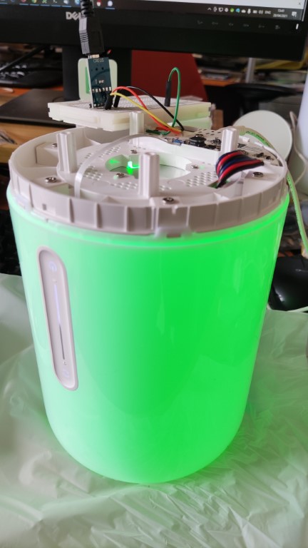
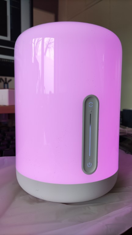
小米®米家床头灯2是一款智能型三色二温(EGBWW) 的 LED 照明灯具,由易来(Yeelight)公司替小米®米家品牌代工。这款灯具可以通过Wi-Fi网络以及该机器前侧的触摸面板来对其进行操控。触摸面板带有电源键、变色键还有一个控制灯光亮度的滑条。
本项目为用户提供客制化后的 ESPHome 组件,使得用户对本照明灯具进行全方位的完全控制,并把本照明灯具加入到您的家居助手(Home Assistant)里成为可能。
功能
-
本照明灯具 与家居助手(Home Assistant)集成十分容易 只需要采用ESPHome加入就可以做到。
-
本照明灯具不再会与米家云(Mijia Cloud)进行通信 采用本固件后,用户可以完全放心,网络传输仅限于使用者的本地网络。这一点也与家居助手(Home Assistant)的理念相吻合,那就是为使用者提供本地家居自动化平台,以个人隐私为重中之重。
-
不用本地局域网控制选项 就能把照明灯具加入到家居助手(Home Assistant)里。这点非常重要,是因为也不知道小米是犯了什么糊涂穷尽了全体成员的智慧拍脑门子决定要移除本机器的本地局域网控制功能,这样极大地破坏了现有的集成环境。
-
夜灯功能支持多重颜色 原固件只支持单一的暖白夜灯颜色。
-
平滑的灯光颜色切换 不像是当前易来(Yeelight)集成版本的那样。Homekit集成的确提供了挺不错的切换,可是在我个人的系统中,在家居助手(Home Assistant)用户界面里缺少色温白光模式。
-
由于本照明灯具的组件是被当做ESPHome组件存在的,用户不需要依照该灯具过去的运行功能来使用 你可以把本照明灯具依照你的偏好添加到你的家居自动化环境里。使用滑条控制您音响系统的音量你喜欢么?长按电源按键把整个屋子变成夜晚模式可以吗?使用滑条的显示面团发酵进度怎么样?好哇,说走就走! (^U^)
-
所有照亮前面板的LED(电源键、变色键和滑条的10颗LED)可以一对一控制 这意味着你有12颗可以依照你的偏好使用的LED,而不需要依照该灯具过去的运行功能来使用。
-
通过硬件模改以扩展机器功能可能性 存在GPIO 针没有被使用。如果你的人送外号是“修改狂人”,你可以利用这些针来想出你自己的硬件妙用来扩展机器的功能。
快速开始指导
对刷ESPHome到机器中有经验的人可以来看看:
- 确保你使用的是ESPHome 2021.10.0或者更加新的版本。
- 复制
example.yaml到<CONFIG_DIR>/<NODE_NAME>.yaml。 - 根据需求自行修改配置文件(详阅 配置指导)。
- 编译
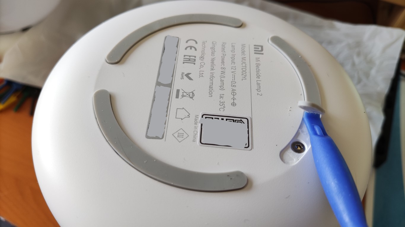
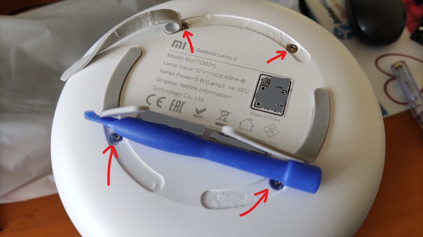
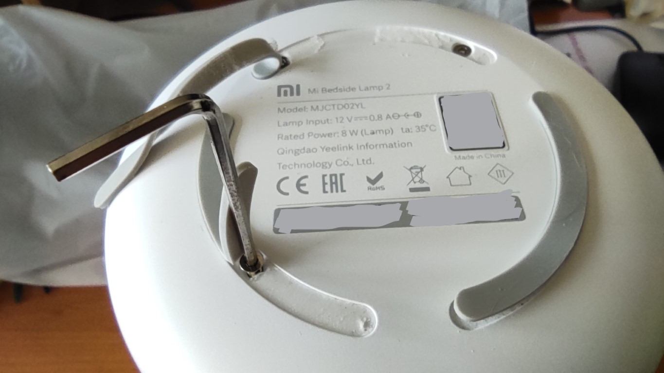
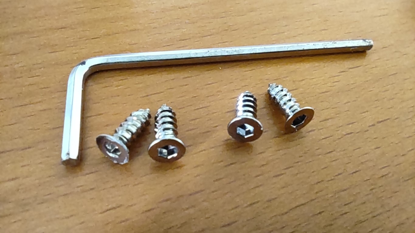
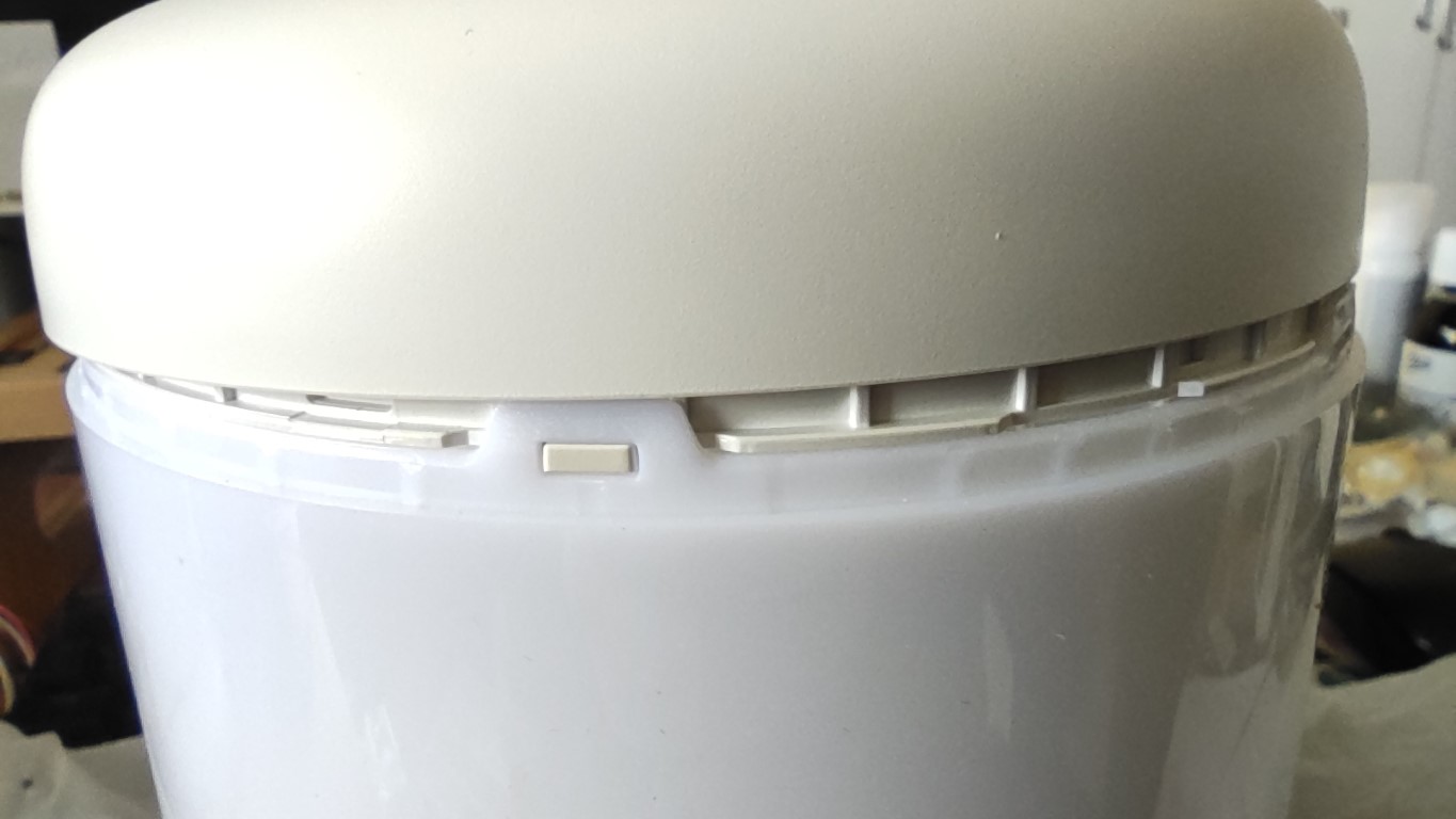
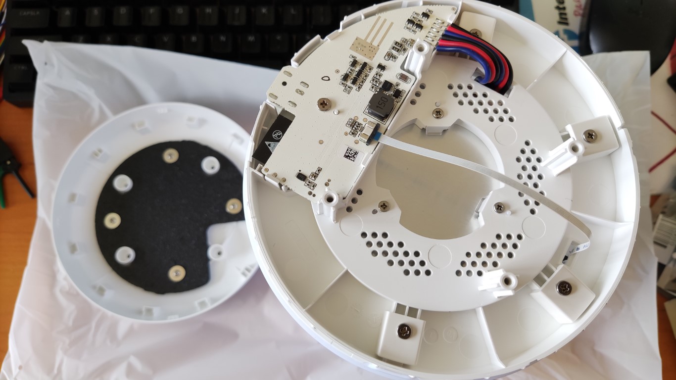
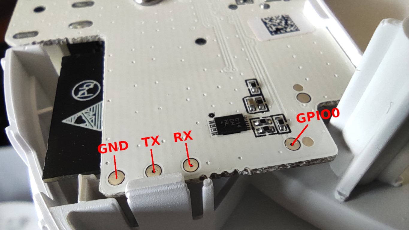
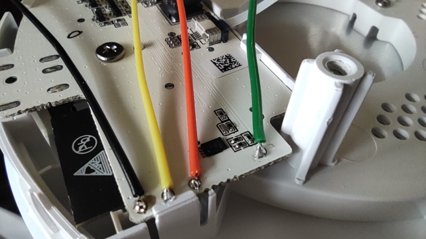
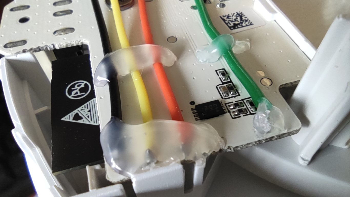
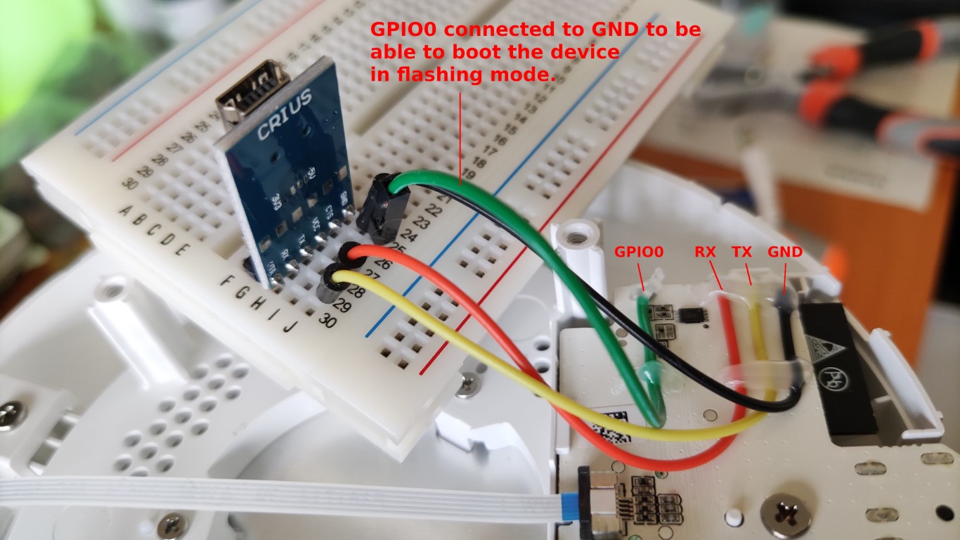
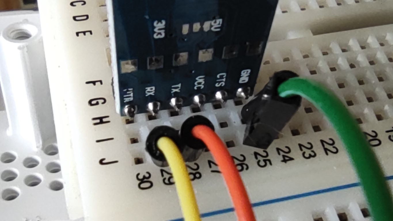
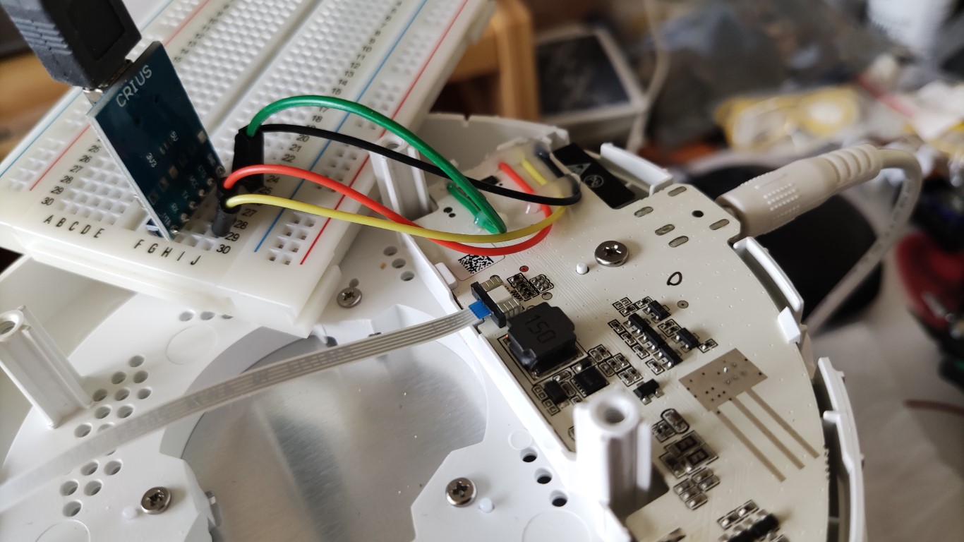
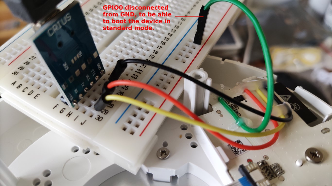
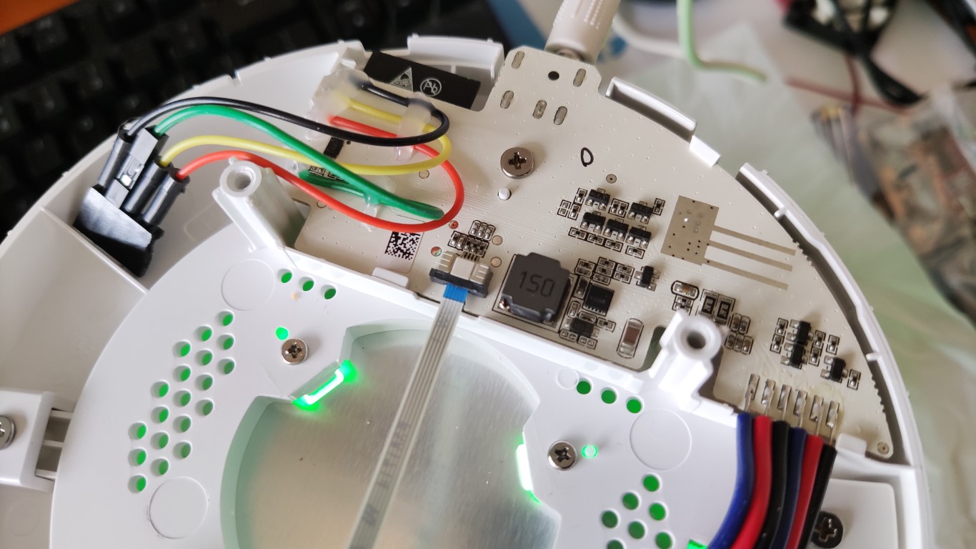
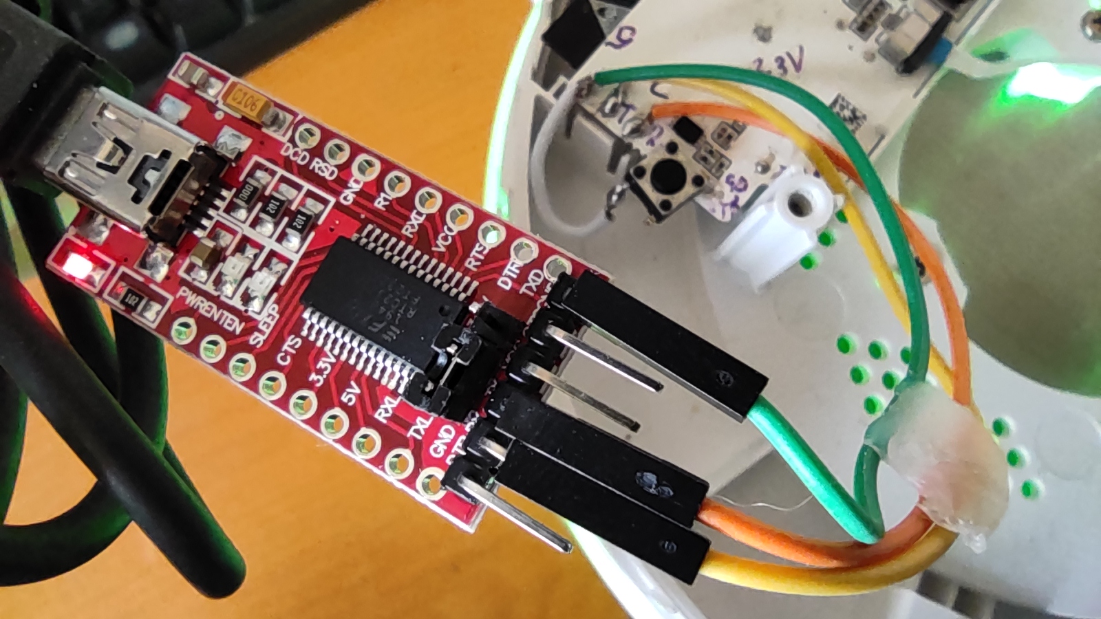
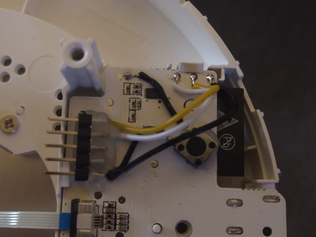
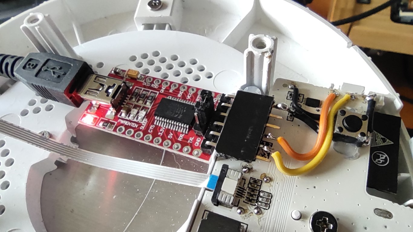
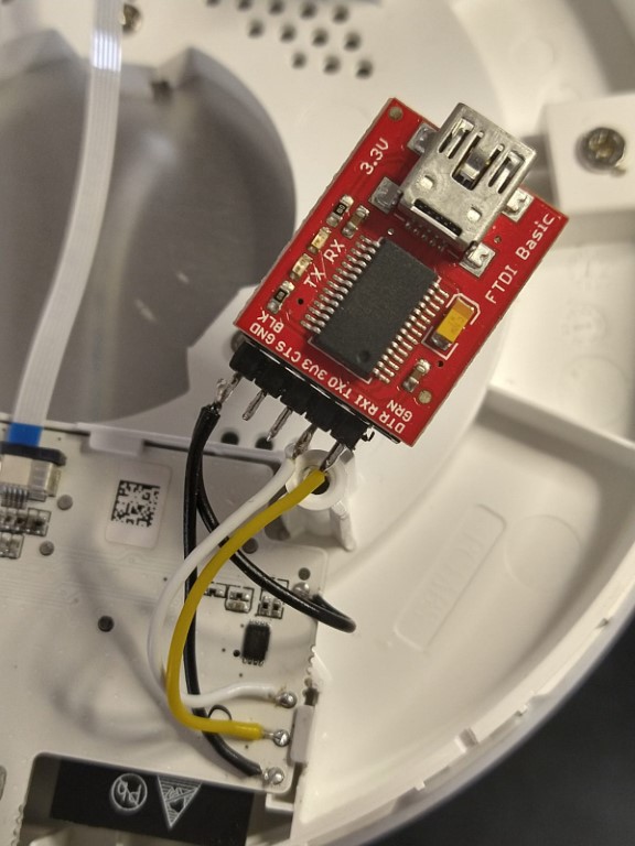
firmware.bin文件并下载到被你连接到串行转USB适配器的机器里。 - 拆灯 连接灯具的
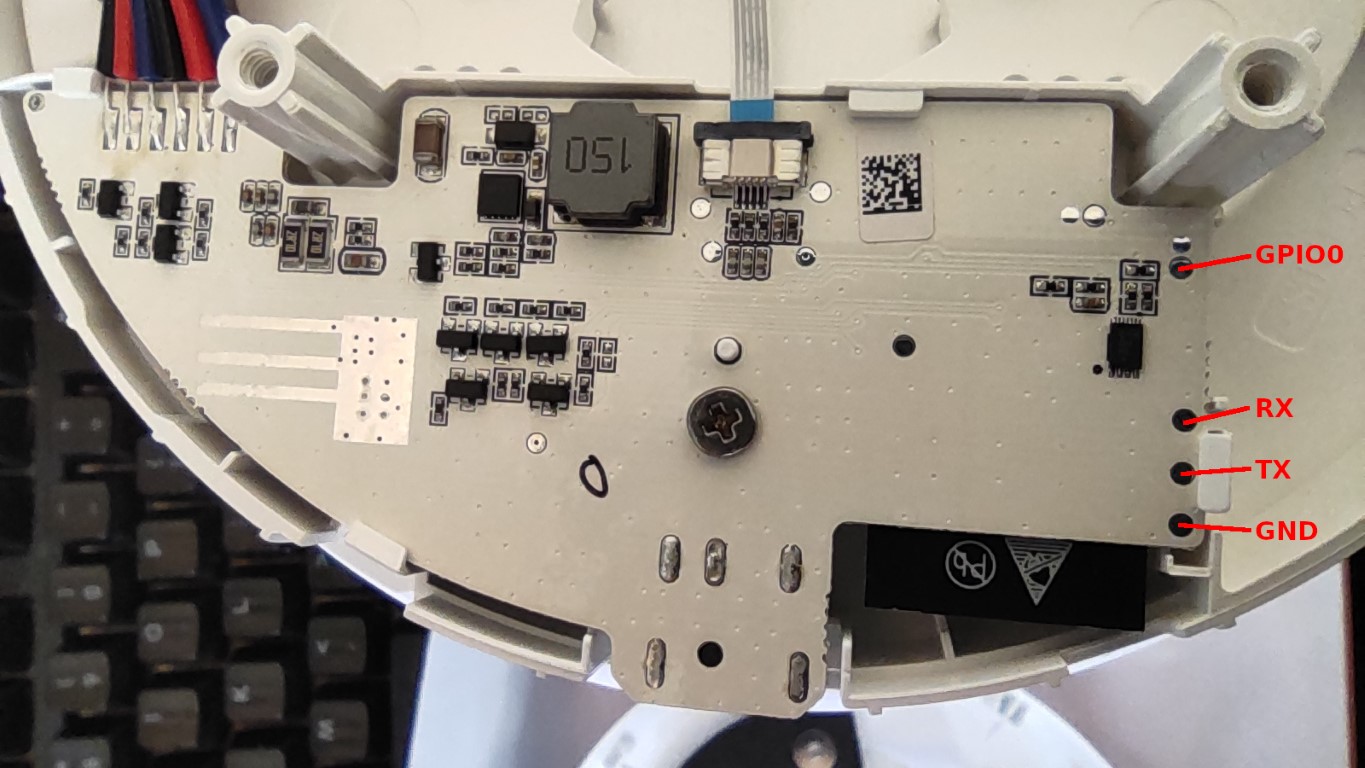
TX,RX,GND和GPIO0调试接点到串行适配器。请看接点的位置图。 - 给本照明灯具通电,
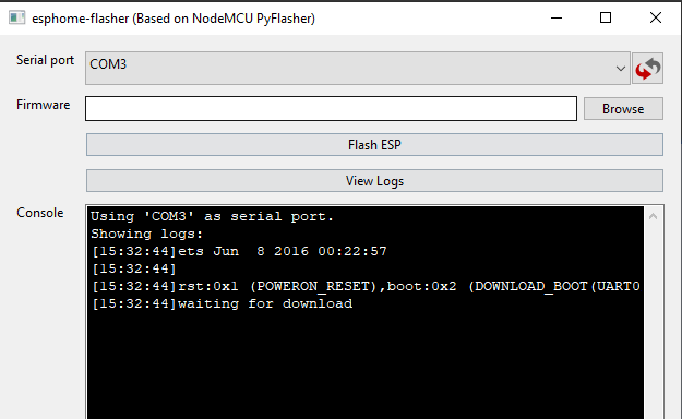
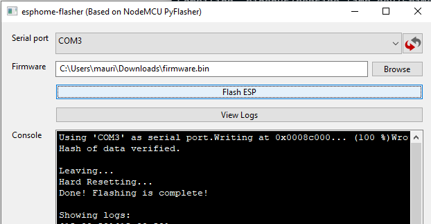
GPIO0要与GND连在一起以启用刷机模式。 - 把
firmware.bin刷进机器,例如使用esphome-flasher。
升级
我总想让这个机器不用进行其他修改就可以升级固件。但有些时候,根本不可能完成。如果升级失败,升级的说明在这里。
 mmakaay
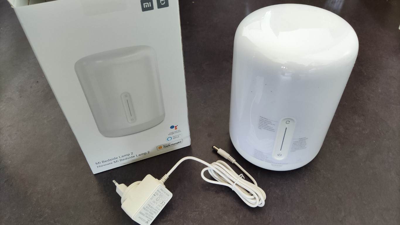

Is your feature request related to a problem? Please describe. I want to translate this project. I find Xiaomi and Yeelight is annoying me. It's been almost a year since i contacted to both Xiaomi and Yeelight. And about one month since i complained to 12315, yet no one want to solve this.
Describe the solution you'd like Me by offering the translation.
Describe alternatives you've considered Google Translate