 severinferard
commented
2 years ago
severinferard
commented
2 years ago After further investigations, it appears that issue can be reproduced while connected to the debug board by touching (with bare fingers or probing with an oscilloscope) the MISO pins, either on the main board or on the ppg shield.
When looking at the MISO signal on an oscilloscope, we can clearly see a voltage drop during the transmission of the data, resulting in bits being perceived as 'zeros' by the master because their voltage is lower than the threshold needed to be read as 'ones'.
The following image is a capture on an oscilloscope of the MISO line and Clock line.
 The 3 spikes which corresponds to 'ones' in the signal should be as high as the initial MISO signal.
FIX
It has been found that lowering the SPI Clock speed can fix the voltage drops issue, thus allowing for a solid connection between the watch and the ppg sensor. Decreasing the CLK frequency from 1 Mhz to 100 khz allows for a stable connection between the watch and the ppg sensor, without the debug board and without hardware modification.
Further investigations
Here are 3 captures of the MISO signal, at respectively 100 Khz, 1 Mhz and 2 Mhz.
100 Khz
 1 Mhz
2 Mhz
1 Mhz
2 Mhz

Here are 3 captures of the MOSI signal, at respectively 100 Khz, 1 Mhz and 2 Mhz.
100 Khz
 1 Mhz
1 Mhz
 2 Mhz
2 Mhz

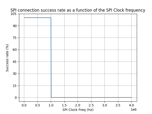
Because the clock speed appears to be the main factor, I've created a test to find the optimal clock speed. The test can be found in test/unit/SPI-clk-speed . By reading the part id register of the max86141 which the value is constant and know, it is possible to plot the SPI read/write success rate depending of the clock speed, thus showing what is the maximum clock speed we can reach before the connection is no longer guaranteed. Results can be found in the 'results' folder.
Connected to the debug board
Not connected to the debug board
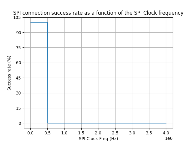
The max clock speed we can set before the connection becomes unstable without the debug board appears to be around 450 Khz.
Describe the bug PPG signal is only received while both part of the watch are connected to the debug board.
To Reproduce
Expected behavior The serial monitor should show the part id of the max86141, not 0.
If the same operation is carried out with both parts of the watch connected to the debug board, the connection works fine and data can be read from the sensor.