mylesagray / blog-comments

Comments for Blah, Cloud. Hugo blog
0 stars 0 forks source link

Fixing/Flashing a broken motherboard w/ SPIPGM2 and Serial | Blah, Cloud #3

Open mylesagray opened 2 years ago

mylesagray commented 2 years ago

Written on 02/01/2012 21:09:18

URL: https://blah.cloud/hardware/fix-broken-motherboard/

mylesagray commented 2 years ago

Comment written by tim on 08/24/2011 12:26:19

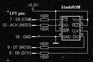
are you sure about that pinout ?
I searched several sites an they state:
(lpt left and spi right)
7 => 5
8 => 6
9 => 4
10 => 3
18 => 8

mylesagray commented 2 years ago

Comment written by Mutant_Tractor on 08/24/2011 12:36:30

Yes 100% sure - this is what I used to fix my own motherboard, and 2 others - just remember not to try and use 2x 1.5v batteries - that won't work, you must use the 3v rail on a PSU.

mylesagray commented 2 years ago

Comment written by tim on 08/24/2011 12:40:11

I see you are using an ASUS board. That would nould a IDC 8pins connector with 2.54mm pitch as the spi header has only 8 pins with the pin at position 8 being absent. On the pictures the cables are connected with the parallel port not the serial port as stated in your post. The pinout in previous post is for msi jspi header wich has 10 pins with 2mm pitch.

mylesagray commented 2 years ago

Comment written by tim on 08/24/2011 12:45:06

what voltages are you getting on the data lines on the parallel port ? pins 7,8,9 & 10 ? I'm using my multimeter on pins 7,8,9 & 10 and pin 8 on the bios chip istself. They are all getting 3.29V but when I use spipgm2 /i it returns FFFFFFh and unknown manufacturer :-s

mylesagray commented 2 years ago

Comment written by Mutant_Tractor on 08/24/2011 12:57:23

Hi Tim,
Yes I meant parallel port - Have you got the port in the right mode in the BIOS?

mylesagray commented 2 years ago

Comment written by tim on 08/24/2011 13:07:11

The port address is 378h and I experimented with the 4 different modes it has:
printer
bidirectional
EPP
ECP
nothing worked. Still kept telling me FFFFFFh and manufacturer unknown. Using the orange pin from my OCZ psu (3.3V directly to Vcc). I can adjust it manually to whithin certain limits (2.84V to 3.84V).

mylesagray commented 2 years ago

Comment written by Mutant_Tractor on 08/24/2011 13:19:21

Have you created your cable as detailed in this diagram?

http://www.megaupload.com/?...

mylesagray commented 2 years ago

Comment written by tim on 08/24/2011 13:28:20

As my mainboard is msi it has a 10 pin idc connector and this is the pinout: http://i240.photobucket.com...

here's the scheme for the cable:
http://i240.photobucket.com...

and here is what my cable looks like more or less (without the capacitor and my cable pins 1 & 2 connected to psu: orange pins ):
http://www.fccps.cz/downloa...

mylesagray commented 2 years ago

Comment written by awaaas on 09/13/2011 22:04:32

Hi there,
I tried your SPIPGM2 tutorial, but it's always say "status=FFh" and "Set WP# pin level high"

I followed the ReflashBIOS.pdf but the result says nothing

Any Ideas?

btw, i use jetway HI04-GT motherboard (a poor man choice to try OC...)

mylesagray commented 2 years ago

Comment written by Mutant_Tractor on 09/14/2011 17:02:49

Hey man,

That means that you aren't using another pc's 3v rail - are you sure that you are jumping the other PSU properly?

Myles

mylesagray commented 2 years ago

Comment written by Elmira on 09/21/2011 03:51:13

Call me wind because I am absolteuly blown away.

mylesagray commented 2 years ago

Comment written by TOMMY on 10/15/2011 09:45:21

Hello.. i got error msg when try to unlock the protection bit using spipgm /u.. its said set WP# high.. on 1 board i can write the bios, but on another board its failed, it could bit the protection bit still locked.. what must i do? thx from Indonesia

mylesagray commented 2 years ago

Comment written by TOMMY on 10/15/2011 09:50:04

i have connect the 3.3vdc from another PSU to pin 1 on the mainboard and GND to pin 8.. pin 7 connected to pin 18 on LPT port.. Did i do something wrong? thx

mylesagray commented 2 years ago

Comment written by Debjit Biswas on 10/19/2011 15:40:14

I have gigabyte 81845gvm-rz , ecs p4m800pro - mv1.0a. and msi ms-7191 ver:1.1 rs482m4this three motherboard and the problem is there can run but no display onto them i think its only for bios .
can You help me How to reinstall that bios?
I want to know what pin i can use , and there only some com port nothing more, can it is possible to flush through lpt to lpt or com port???/
Please reply this post, it will be very grate full for me.
thanks.

mylesagray commented 2 years ago

Comment written by Matt on 11/11/2011 20:29:11

Let me put the long story short. I tried to extract a dell bios from this hp pc and ended up in corrupted bios. After that there is no video no beep. I have tried everything in the hp support website( the machine is out of warranty).

PC Model: HP Compaq Microtower PC dx7500

Motherboard : IPIEL-LA Rev3
Bios : AMI

When I start the machine there is no video no power LED, no beeps at all. The only activity this machine does is to read the cd drive, as read in many forums, I downloaded the bios from this link

http://h20000.www2.hp.com/b...

extracted it and found a file named EUR5.14 using a hex editor i opened this file and searched for a ROM and found it is looking for HPBIOS.ROM in the motherboard manual; they say to format a usb in fat or fat32 and place this ROM file in the usb disk and start computer. Nothing worked for me. I tried cd's, bootable cd's etc. some times when I press ctrl+home the system reboots as I figured out from the CPU fan and it seeks in the cd drive for few seconds and does nothing. I found a floppy drive and a floppy disk with the files in it plugged it into the motherboard 34-pin connecter but it never tries to read. Now I assume that its unable to recover itself. ( I tried AMIBOOT.ROM as well). Please help me to ressurrect my PC.

I appreciate your time and helpfulness.

mylesagray commented 2 years ago

Comment written by Elliott on 01/26/2012 03:25:45

Oh My GOD! You just help me save my DFI Lanparty x48! THANK YOU times a million! It took several tries to figure out that I needed a delay /d=256. Also, the pin-out on the DFI is different, but it's published in the manual. But it WORKED! And I just did an AWDFLASH to get it up to the most recent bios, so it really looks good. Thank you for saving me! Now I just have to get it all back in case. :-)

mylesagray commented 2 years ago

Comment written by Enrique Vago on 11/02/2014 02:15:15

For those who are with the error Set WP # Please check the address LPT port in the bios on pc is set to 378 ok !

I changed here and worked !

Nice

Tks

mylesagray commented 2 years ago

Comment written by Steve Dougherty on 12/13/2014 06:46:27

Why are you saying in your guide to use a separate / spare PSU altogether *ONLY* for supplying the 3.3v line? Why not simply tap into the orange 3.3 volt line on the recovery PC' s own PSU, negating the need to use a second PSU???

/scratches head.

mylesagray commented 2 years ago

Comment written by Myles Gray on 12/13/2014 21:12:03

You misunderstand Steve, it's to say use a PSU for the 3.3v line, don't try and piggy-back some AA batteries to do it.

mylesagray commented 2 years ago

Comment written by Steve Dougherty on 12/13/2014 23:18:12

Yeah I figured as much, only if your recovery system is a desktop (not a laptop as you cant tap into a laptops 3.3v line), then you don't need a spare psu to jump wire, you can simply tap into the desktop recovery's 3.3v lines on the 24-pin ATX header, right?

mylesagray commented 2 years ago

Comment written by Myles Gray on 12/13/2014 23:20:18

Yep not a problem there, should work fine, it was stated as my recovery system was a laptop.

mylesagray commented 2 years ago

Comment written by Dylan Morshead on 02/17/2015 08:16:28

Is there a way to do it though USB, i no longer have a parallel computer.

mylesagray commented 2 years ago

Comment written by julius on 04/24/2016 03:41:20

you forgot to put capacitor on input voltage

mylesagray commented 2 years ago

Comment written by Ashaan Ramdial on 10/05/2017 23:38:39

Hi there

Please can you update the links as I need to create this cable and use this software to unbrick my Intel dg45id motherboard.