nRF24 / RF24Ethernet

OSI Layers 4&5 Wireless (not WiFi) TCP/IP networking on Arduino devices using nrf24l01+ & nrf52x radios
http://nrf24.github.io/RF24Ethernet
119 stars 50 forks source link

Communication Issue between SLIP_InteractiveServer and SLIP_Gateway #23

Open RSABear opened 3 years ago

RSABear commented 3 years ago

I am using the latest code downloaded from GitHub. I have very little nRF24 experience and using the libraries to learn. I successfully covered all the examples over the last few weeks up to the RF24Ethernet SLIP_InteractiveServer and SLIP_Gateway. I have made no code changes to the examples, except put a radio.printDetails() in the code to show the configuration. From the documentation it seems the problem is RX_ADDR_P0-1 in the SLIP_InteractiveServer code. I ask your assistance to help correct the addresses. RF24Ethernet SLIP_InteractiveServer: image RF24Ethernet SLIP_Gateway: image

/*
 * RF24Ethernet Webserver controlling an LED example *
 *
 * **NOTE: This example demonstrates usage the SLIP_Gateway
 *   When using SLIP, there are 3 main differences:
 *    1. The RF24Mesh layer must be used to provide MAC/IP translation
 *    2. The specified RF24Mesh nodeID must be the same as the last octet of the IP
 *        ie: IP: 192.168.1.2  NodeId must be 2
 *
 *    3. The RF24Ethernet library must be configured for TUN
 *       a: Open the uip_conf.h file, make sure to #define UIP_CONF_LLH_LEN 0
 *
 * The following commands must be run on the Linux device to enable slip
 * 1. Connect your Arduino
 * 2. On RPi, cd /dev
 * 3. Type 'ls' and look for a new device ttyUSB<X> where <X> is a number
 * 4. Run   sudo modprobe slip
 * 5. Run   sudo slattach -L -s 115200 -p slip /dev/ttyUSB<X> &
 * 6. Run   sudo ifconfig s<X> 10.10.3.1 dstaddr 10.10.3.2
 * 7. Run   sudo route add -net 10.10.3.0/24 gw 10.10.3.1

 * RF24Ethernet uses the uIP stack by Adam Dunkels <adam@sics.se>
 *
 * This example demonstrates how to configure a sensor node to act as a webserver and
 * allows a user to control a connected LED by clicking links on the webpage
 * The requested URL is used as input, to determine whether to turn the LED off or on
 */

#include <RF24Network.h>
#include <RF24.h>
#include <SPI.h>
#include <printf.h>
#include <RF24Ethernet.h>
#include "HTML.h"

// Include RF24Mesh and the EEPROM libs
#include "RF24Mesh.h"
#include "EEPROM.h"

/*** Configure the radio CE & CS pins ***/
RF24 radio(7,8);
RF24Network network(radio);
RF24Mesh mesh(radio,network);
RF24EthernetClass RF24Ethernet(radio,network,mesh);

#define LED_PIN A3 //Analog pin A3

// Configure the server to listen on port 1000
EthernetServer server = EthernetServer(1000);

/**********************************************************/

void setup() {
  // Set up the speed of our serial link.
  Serial.begin(115200);
  printf_begin();
  Serial.println("start");
  pinMode(LED_PIN, OUTPUT);

  // This step is very important. When using TUN or SLIP, the IP of the device
  // must be configured as the NodeID in the RF24Mesh layer

  mesh.setNodeID(2);
  mesh.begin();

  //Optional
  radio.printDetails();

  // Set the IP address we'll be using.  Make sure this doesn't conflict with
  // any IP addresses or subnets on your LAN or you won't be able to connect to
  // either the Arduino or your LAN...

  // NOTE: The last octet/last digit of the IP must match the RF24Mesh nodeID above
  IPAddress myIP(10, 10, 3, 2);
  Ethernet.begin(myIP);

  // If you'll be making outgoing connections from the Arduino to the rest of
  // the world, you'll need a gateway set up.
  IPAddress gwIP(10, 10, 3, 1);
  Ethernet.set_gateway(gwIP);

  // Listen for incoming connections on TCP port 1000.
  server.begin();

}

/********************************************************/

uint32_t mesh_timer = 0;

void loop() {

  // This is the last of the differences between this and the regular Interactive Server example
  // If the master node is completely down, and unresponsive for 30 seconds, renew the address

  if(millis()-mesh_timer > 30000){ //Every 30 seconds, test mesh connectivity

    mesh_timer = millis();

    if( ! mesh.checkConnection() ){
        //refresh the network address        
        mesh.renewAddress();

     }
  }

  size_t size;

  if (EthernetClient client = server.available())
  {
    uint8_t pageReq = 0;
    generate_tcp_stats();
    while ((size = client.available()) > 0)
    {
      // If a request is received with enough characters, search for the / character
      if (size >= 7) {
        char slash[] = {"/"};
        client.findUntil(slash, slash);
        char buf[3] = {"  "};
        buf[0] = client.read();  // Read in the first two characters from the request
        buf[1] = client.read();

        if (strcmp(buf, "ON") == 0) { // If the user requested http://ip-of-node:1000/ON
          led_state = 1;
          pageReq = 1;
          digitalWrite(LED_PIN, led_state);

        }else if (strcmp(buf, "OF") == 0) { // If the user requested http://ip-of-node:1000/OF
          led_state = 0;
          pageReq = 1;
          digitalWrite(LED_PIN, led_state);

        }else if (strcmp(buf, "ST") == 0) { // If the user requested http://ip-of-node:1000/OF
          pageReq = 2;

        }else if (strcmp(buf, "CR") == 0) { // If the user requested http://ip-of-node:1000/OF
          pageReq = 3;

        }else if(buf[0] == ' '){
          pageReq = 4; 
        }
      }
      // Empty the rest of the data from the client
      while (client.waitAvailable()) {
        client.read();
      }
    }

    /**
    * Based on the incoming URL request, send the correct page to the client
    * see HTML.h
    */
    switch(pageReq){
       case 2: stats_page(client); break;
       case 3: credits_page(client); break;
       case 4: main_page(client); break;
       case 1: main_page(client); break;
       default: break; 
    }    

    client.stop();
    Serial.println(F("********"));

  }

  // We can do other things in the loop, but be aware that the loop will
  // briefly pause while IP data is being processed.

  int save_led_state = led_state;

  for(int i=0; i<10; i++){
    digitalWrite(LED_PIN, 1);
    delay(50);
    digitalWrite(LED_PIN, 0);
    delay(50);
    }

  digitalWrite(LED_PIN, save_led_state);  

}

/**
* This section displays some basic connection stats via Serial and demonstrates
* how to interact directly with the uIP TCP/IP stack
* See the uIP documentation for more info
*/
static unsigned short generate_tcp_stats()
{
  struct uip_conn *conn;

  // If multiple connections are enabled, get info for each active connection
  for (uint8_t i = 0; i < UIP_CONF_MAX_CONNECTIONS; i++) {
    conn = &uip_conns[i];

    // If there is an open connection to one of the listening ports, print the info
    // This logic seems to be backwards?
    if (uip_stopped(conn)) {
      Serial.print(F("Connection no "));
      Serial.println(i);
      Serial.print(F("Local Port "));
      Serial.println(htons(conn->lport));
      Serial.print(F("Remote IP/Port "));
      Serial.print(htons(conn->ripaddr[0]) >> 8);
      Serial.print(F("."));
      Serial.print(htons(conn->ripaddr[0]) & 0xff);
      Serial.print(F("."));
      Serial.print(htons(conn->ripaddr[1]) >> 8);
      Serial.print(F("."));
      Serial.print(htons(conn->ripaddr[1]) & 0xff);
      Serial.print(F(":"));
      Serial.println(htons(conn->rport));
      Serial.print(F("Outstanding "));
      Serial.println((uip_outstanding(conn)) ? '*' : ' ');

    }
  }
  return 1;
}
TMRh20 commented 
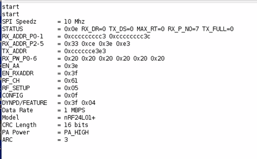
3 years ago

The RX_ADDR_P0-1 address is fine, not sure what the problem would be. The SLIP examples never worked very well, really just a proof of concept, it’s recommended to use a raspberry Pi as the gateway with RF24gateway.

On Apr 4, 2021, at 12:30 PM, Bernard van der Nest @.***> wrote:

 I am using the latest code downloaded from GitHub. I have very little nRF24 experience and using the libraries to learn. I successfully covered all the examples over the last few weeks up to the RF24Ethernet SLIP_InteractiveServer and SLIP_Gateway. I have made no code changes to the examples, except put a radio.printDetails() in the code to show the configuration. From the documentation it seems the problem is RX_ADDR_P0-1 in the SLIP_InteractiveServer code. I ask your assistance to help correct the addresses. RF24Ethernet SLIP_InteractiveServer:

RF24Ethernet SLIP_Gateway:

— You are receiving this because you are subscribed to this thread. Reply to this email directly, view it on GitHub, or unsubscribe.

RSABear commented 3 years ago

I don't know anybody who did not curse SLIP when we used it in the 90s to network systems. I have some RPis, will hook the demo gateway up on one. Your effort in expanding the nRF24 library code over years is highly appreciated.

RSABear commented 3 years ago

@TMRh20 - I have the SLIP example bug fixed and working, I understand the code now much better. I will post the working code shortly. image image

RSABear commented 3 years ago

I have modified the example code and stripped out everything that was not needed as below. It only works while you are sending GET requests via a browser, Postman or curl. If you leave the the InteractiveServer running for a few minutes then it dies. A quick disconnect and connect on the serial port and all runs well again. It seems that when there are no packets flowing or something it quits life. I am not sure I want to continue with the example code as the model is not what I require, I only did this because it was not working at all and I wanted to learn as much as possible. I might come back to this when time permits. I need a very remote Nano Node to be a SLIP client opening a SLIP connection (or simpler) to the Gateway as a server, make a MqTT connection via the PubSub Lib, publish and receive a couple of messages and then disconnect.

RF24Ethernet Serial Gateway Example using SLIP

/*
 * The code was modified to work with 2 x Arduino Mega 2560 board for development purposes.
 *  
 * RF24Ethernet Serial Gateway Example using SLIP *
 * This example will allow RF24Ethernet to be used with any device capable of the SLIP protocol
 *
 * When using SLIP, there are 3 main differences to the SLIP_Gateway:
 *    1. The RF24Mesh layer is used to provide MAC/IP translation
 *    2. The Master node will always have a NodeID of 0, and the IPV4 address for the Master 
 *       in this example is defined as 10.0.3.1
 *    2. The child nodes The specified RF24Mesh nodeID must be the same as the last octet of the IP
 *        ie: IP: 10.0.3.2  NodeId must be 2
 * *    3. The RF24Ethernet library must be configured for TUN
 *       a: Open the uip-conf.h file in the RF24Ethernet directory and set the #define UIP_CONF_LLH_LEN 0
 *
 * The following commands must be run on the Linux device to enable slip
 * 1. On Linux the ports are created in the dev directory, cd /dev
 * 2. Type 'ls' , note the ttyUSB<X> devices
 * 3. Connect your Arduino
 * 4. Type 'ls' and look for a new device ttyUSB<X> where <X> is a number
 * 5. Run   sudo modprobe slip
 * 6. Run   sudo slattach -L -s 115200 -p slip /dev/ttyUSB<X> &
 * 7. Note the & at the end of the previous command. This will run slattach in the background,
 *    without it, slattach will appear to hang and CTRL+C will exit.
 * 7. Run ifconfig , note the sl<X> device
 * 8. Run   sudo ifconfig sl<X> 10.10.3.1
 * 9. Run   sudo route add -net 10.10.3.0/24 gw 10.10.3.1
 * 10. The gateway is now up and running. Active RF24Ethernet nodes should be pingable.

  - Scripts used on Linux
    sudo modprobe slip
    sudo sysctl -w net.ipv4.ip_forward=1
    sudo slattach -L -s 115200 -p slip /dev/ttyACM0 &
    sudo ifconfig sl0 10.10.3.1 dstaddr 10.10.3.2

 Note: If using an ip of 192.168.3.1 for the gateway, the commands are very similar:
        ie: sudo route add -net 192.168.3.0/24 gw 192.168.3.1

 * RF24Ethernet uses the uIP stack by Adam Dunkels <adam@sics.se>
 *
 * This example demonstrates how to configure a sensor node to act as a webserver and
 * allows a user to control a connected LED by clicking links on the webpage
 *
 * The requested URL is used as input, to determine whether to turn the LED off or on
 *
 * Debug Settings:
 * This example uses a second Serial Port - Serial1 to print the debug information to 
 * in order not to interfere with the SLIP network
 * Connect a FTDI or Foca Pro to PINs 18 & 19 as well as GND
 * The Serial Port on Linux will appear in the /dev directory as /dev/ttyUSB0 or higher
 * number if you have more serial devices connected.
 * Edit prinf.h in the RF24 directory
 * */

#include <SPI.h>
#include <RF24.h>
#include <RF24Network.h>
#include <RF24Mesh.h>
#include <printf.h>

/**** Configure the nRF24L01 CE and CS pins ****/
RF24 radio(7, 8);
RF24Network network(radio);
RF24Mesh mesh(radio, network);

// Comment the following define out if no debug is needed
#define         SLIP_DEBUG_LED          // Will delay and flash LEDs if unable to find a node by IP address ( node needs to reconnect via RF24Mesh ) 
#define         SLIP_DEBUG_SERIAL       // Serial Output

// Define the LED pins
// #define DEBUG_LED_PIN A3
#define         DEBUG_LED_PIN   40
#define     SLIP_TXRX_LED_PIN   41
#define  NETWORK_TXRX_LED_PIN   42

// Connect LED Cathode to the PIN and the Anode via a LED resistor to Vcc (sink mode)
#define               LED_OFF   1
#define               LED_ON    0

// NOTE: IMPORTANT this should be set to the same value as the UIP_BUFSIZE and
// the MAX_PAYLOAD_SIZE in RF24Network. The default is 120 bytes
#define UIP_BUFFER_SIZE MAX_PAYLOAD_SIZE

// Global variables
uint8_t slip_buf[UIP_BUFFER_SIZE]; // MSS + TCP Header Length

uint32_t mesh_timer = 0;
uint32_t mesh_time = 30000;          // Every 30 seconds, test mesh connectivity
uint32_t debug_info_timer = 0;
uint32_t debug_info_time = 30000;    // Every 30 seconds, we display the debug information

//Function to send incoming network data to the SLIP interface
void networkToSLIP();

void setup() {

  SPI.begin();
  radio.begin();

  Serial.begin(115200);
  while (!Serial) {
    // some boards need to wait to ensure access to serial over USB
    // We will use this Serial Port for SLIP <-> NETWORK messages
  }

#if defined SLIP_DEBUG_SERIAL
  Serial1.begin(115200);
  while (!Serial1) {
    // some boards need to wait to ensure access to serial over USB
    // We will use this Serial Port for Debug Messages
    // Foca Pro connected to GND, PIN 18 & PIN 19, /dev/ttyUSB0
  }
  printf_begin();             // Call once, setup for printing debug information to Serial Port 1

  Serial1.println();
  Serial1.print(F("RF24_SLIP_Gateway\n"));
#endif

  // Set this to the master node (nodeID 0)
  mesh.setNodeID(0);
  mesh.begin();

  // Use Serial as the SLIP device
  slipdev_init(Serial);

  pinMode(53, OUTPUT);                      // Mega 2560 SPI Library fix

  // Start-up signal - make sure our LED's are working
#if defined SLIP_DEBUG_LED

// Debug LED stuff
  pinMode(DEBUG_LED_PIN, OUTPUT);
  pinMode(SLIP_TXRX_LED_PIN, OUTPUT);       //    SLIP -> Network
  pinMode(NETWORK_TXRX_LED_PIN, OUTPUT);    // Network -> SLIP

  for (int i=0; i<5; i++){
    digitalWrite(DEBUG_LED_PIN, LED_ON);
    digitalWrite(SLIP_TXRX_LED_PIN, LED_ON);
    digitalWrite(NETWORK_TXRX_LED_PIN, LED_ON);
    delay(50);
    digitalWrite(DEBUG_LED_PIN, LED_OFF);
    digitalWrite(SLIP_TXRX_LED_PIN, LED_OFF);
    digitalWrite(NETWORK_TXRX_LED_PIN, LED_OFF);
    delay(50);
  }
#endif

  // Radio Settings
  radio.setPALevel(RF24_PA_MIN, false);

#if defined SLIP_DEBUG_SERIAL
  // //Debug information
  Serial.println(F("**** RF24 Radio Information ****"));
  radio.printDetails();       // (smaller) function that prints raw register values
  // radio.printPrettyDetails(); // (larger) function that prints human readable data
  Serial.println(F("********************************"));
#endif

}

void loop() {

  // Call mesh.update to keep the network updated
  mesh.update();

  // In addition, keep the 'DHCP service' running on the master node so addresses will
  // be assigned to the sensor nodes
  mesh.DHCP();

  // Provide RF24Network addresses to connecting & reconnecting nodes
  if((millis()-mesh_timer)>mesh_time){
    mesh_timer = millis();
    mesh.DHCP();
  }

  if((millis()-debug_info_timer)>debug_info_time){        // Every ss seconds, display the debug values
    debug_info_timer = millis();
    #if defined SLIP_DEBUG_SERIAL
      Serial1.println(F("**** RF24Mesh Assigned Addresses ****"));
    for(int i=0; i<mesh.addrListTop; i++){
      Serial1.print("NodeID: ");
      Serial1.print(mesh.addrList[i].nodeID);
      Serial1.print(" RF24Network Address: 0");
      Serial1.println(mesh.addrList[i].address,OCT);
    }
    Serial1.println(F("*************************************"));
    #endif
  }

  //Ensure any incoming user payloads are read from the buffer
  while(network.available()){
    RF24NetworkHeader header;
    network.read(header,0,0);    
  }

  // Handle external (TCP) data
  // Note: If not utilizing RF24Network payloads directly, users can edit the RF24Network_config.h file
  // and uncomment #define DISABLE_USER_PAYLOADS. This can save a few hundred bytes of RAM.
  if(network.update() == EXTERNAL_DATA_TYPE) {
    networkToSLIP();
  }

  // Poll the SLIP device for incoming data
  //uint16_t len = slipdev_poll();
  uint16_t len;
  if( (len = slipdev_poll()) > 0 ){
    if(len > MAX_PAYLOAD_SIZE){ 
        return; 
        }

    #if defined SLIP_DEBUG_LED
      digitalWrite(SLIP_TXRX_LED_PIN, LED_ON);
    #endif

    RF24NetworkHeader header(01, EXTERNAL_DATA_TYPE);    
    uint8_t meshAddr;

    // Get the last octet of the destination IP address
    uint8_t lastOctet = slip_buf[19];

    //Convert the IP into an RF24Network Mac address
    if ( (meshAddr = mesh.getAddress(lastOctet)) > 0) {

      // Set the RF24Network address in the header
      header.to_node = meshAddr;

      #if defined SLIP_DEBUG_LED
        digitalWrite(SLIP_TXRX_LED_PIN, LED_OFF);
      #endif

      network.write(header, &slip_buf, len);

    } 
    else {
        // If nodeID/IP not found in address list, the node would need to renew its address
        // Flash the LED 3 times slowly
        #if defined SLIP_DEBUG_LED
          flashLED();
        #endif
    }
   }
}

void networkToSLIP(){

    #if defined SLIP_DEBUG_LED
      digitalWrite(NETWORK_TXRX_LED_PIN, LED_ON);
    #endif

    RF24NetworkFrame *frame = network.frag_ptr;
    size_t size = frame->message_size;
    uint8_t *pointer = frame->message_buffer;
    slipdev_send(pointer, size);

    #if defined SLIP_DEBUG_SERIAL
      Serial1.print(F("ADDR not found\n"));
    #endif

    #if defined SLIP_DEBUG_LED
      digitalWrite(NETWORK_TXRX_LED_PIN, LED_OFF);
    #endif

}

void flashLED() {

  for (int i=0; i<6; i++){
    digitalWrite(DEBUG_LED_PIN, !digitalRead(DEBUG_LED_PIN));
    delay(200);
  }

}

RF24_SLIP_InteractiveServer

/*
 * Configuration for Arduino Mega 2560
 * SPI https://www.arduino.cc/en/Reference/SPI
 * Mega 2560
 * nFR24L01
 * 
 *    GND - 1 *  * 2 - +Vcc
 *     CE - 3 *  * 4 - CNS
 *    SCK - 5 *  * 6 - MOSI 
 *   MISO - 7 *  * 8 - IRQ
 * 
 *  With adapter YL-105
 * 
 *  1 - CE       Mega 2560 PIN 7       Yellow
 *  2 - CSN      Mega 2560 PIN 8       Orange
 *  3 - SCK      Mega 2560 PIN 52      Green
 *  4 - MOSI     Mega 2560 PIN 51      Blue
 *  5 - MISO     Mega 2560 PIN 50      Purple
 *  6 - IRQ      NC                    White
 * 
 * MOSI=ICSP-4 or 51, MISO=ICSP-1 or 50, SCK=ICSP-3 or 52, SS=53
 * 
 *            MISO - 1 *  * 2 - +Vcc
 *            SCK  - 3 *  * 4 - MOSI
 *           Reset - 5 *  * 6 - GND
 * 
 * Insure that PIN 53 is set as Output on the Mega 2560 for the SPI Library
 * 
 * The RF24_SLIP_InteractiveServer is a sample Webserver controlling an LED.
 * Please see the RF24_SLIP_Gateway sketch for the reciprocal settings. 
 *
 * * This example demonstrates how to configure a sensor node to act as a webserver and
 * allows a user to control a connected LED by clicking links on the webpage
 * The requested URL is used as input, to turn the LED OFF or ON, or show some statistics.
 * 
 * Call with:
 * http://10.10.3.2:1000/ON
 * http://10.10.3.2:1000/OFF
 */

#include <SPI.h>
#include <RF24.h>
#include <RF24Network.h>
#include <RF24Ethernet.h>
#include <printf.h>

// Include RF24Mesh and the EEPROM libs
#include "RF24Mesh.h"
#include "EEPROM.h"

/*** Configure the radio CE & CS pins ***/
RF24 radio(7,8);
RF24Network network(radio);
RF24Mesh mesh(radio, network);
RF24EthernetClass RF24Ethernet(radio, network, mesh);

// If debug information is not required comment the following line out
#define SERVER_DEBUG

// #define LED_PIN A3              // Analog pin A3
#define LED_PIN       40           // For Arduino Mega 2560 LED 1 (Blue) 
#define DEBUG_LED_PIN 41           // For Arduino Mega 2560 LED 2 (Red)

// State of the LED in words
String  led_state;

// Connect LED Cathode to the PIN and the Anode via a LED resistor to Vcc (sink mode)
#define LED_OFF       1
#define LED_ON        0  

// Configure the server to listen on port 1000
EthernetServer server = EthernetServer(1000);

// Global variables
uint32_t       mesh_timer = 0;
uint32_t       mesh_time = 30000;          // Every 30 seconds, test mesh connectivity

uint32_t       debug_timer = 0;
uint32_t       debug_time = 10000;          // Every 1S seconds, give us a pulse

uint16_t       led_control = 0;
uint32_t       led_timer = 0;
uint32_t       led_time = 1000;             // Every 1 second - ON/OFF

String client_Req;
char req_index = 0;                         // index into the Client HTTP request buffer

/**********************************************************/
void setup() {

  // Set up the speed of our serial link.
  Serial.begin(115200);
  while (!Serial) {
    // some boards need to wait to ensure access to serial over USB
    // We will use this Serial Port for debug messages
  }
  // printf_begin();  // Required to get the printDetails() to display the values

  Serial.println();
  Serial.println("RF24_SLIP_InteractiveServer Start");

  pinMode(LED_PIN, OUTPUT);
  pinMode(DEBUG_LED_PIN, OUTPUT);
  pinMode(53, OUTPUT);

  // Start-up signal - make sure our LEDs are working
#if defined SERVER_DEBUG
  for (int i=0; i<5; i++){
    digitalWrite(DEBUG_LED_PIN, LED_ON);
    digitalWrite(LED_PIN, LED_ON);
    delay(50);
    digitalWrite(DEBUG_LED_PIN, LED_OFF);
    digitalWrite(LED_PIN, LED_OFF);
    delay(50);
  }
#else
  for (int i=0; i<5; i++){
    digitalWrite(LED_PIN, LED_ON);
    delay(50);
    digitalWrite(LED_PIN, LED_OFF);
    delay(50);
  }
#endif

  // This step is very important. 
  // When using TUN or SLIP, the IP of the device must be 
  // configured as a NodeID in the RF24Mesh layer
  mesh.setNodeID(2);
  mesh.begin();

  // Radio Settings
  radio.setPALevel(RF24_PA_MIN, false);

#if defined SERVER_DEBUG
  // Debug information
  // Serial.println(F("**** RF24 Radio Information ****"));
  // radio.printDetails();          // (smaller) function that prints raw register values
  // radio.printPrettyDetails(); // (larger) function that prints human readable data
  // Serial.println(F("********************************"));
#endif

  // Set the IP address we'll be using.  Make sure this doesn't conflict with
  // any IP addresses or subnets on your LAN or you won't be able to connect to
  // either the Arduino or your LAN...

  // NOTE: The last octet/last digit of the IP must match the RF24Mesh nodeID above
  IPAddress myIP(10, 10, 3, 2);
  Ethernet.begin(myIP);

  // If you'll be making outgoing connections from the Arduino to the rest of
  // the world, you'll need a gateway set up.
  IPAddress gwIP(10, 10, 3, 1);
  Ethernet.set_gateway(gwIP);

  // Listen for incoming connections on TCP port 1000.
  server.begin();

  // Initial state of the LED
  digitalWrite(LED_PIN, LED_OFF);
  led_state = "OFF";

}

/********************************************************/
void loop() {

/*
  if(millis()-debug_timer > debug_time){                  // Every ss seconds, test mesh connectivity
    debug_timer = millis();
    }
*/

  if(millis()-led_timer > led_time){                  // Pulse...
    led_timer = millis();
      if (led_control) {
        digitalWrite(DEBUG_LED_PIN, LED_ON);
        led_control = 0;
      } else {
        digitalWrite(DEBUG_LED_PIN, LED_OFF);
        led_control = 1;
    }
  }

  // For some reason the Network stops working....
  mesh.update();        // Mesh update
  // network.update();
  // Ethernet.update();    // Keep the network stack updated

  // This is the last of the differences between this and the regular Interactive Server example
  // If the master node is completely down, and unresponsive for 30 seconds, renew the address
    if(millis()-mesh_timer > mesh_time){                  // Every ss seconds, test mesh connectivity
      mesh_timer = millis();
      if( ! mesh.checkConnection() ){
        mesh.renewAddress();                              //refresh the network address
        #if defined SERVER_DEBUG
          for (int i=0; i<5; i++){
            digitalWrite(DEBUG_LED_PIN, LED_ON);
            delay(50);
            digitalWrite(DEBUG_LED_PIN, LED_OFF);
            delay(50);
            }
        #endif
      }
    }

  EthernetClient client = server.available(); 
  if (client) { 
      Serial.println("Cient connect");
      boolean endofRequest = true;
      req_index=0;
      while (client.connected()) {
          if (client.available()) {   
              char c = client.read(); 
              if (client_Req.length() < 128) {          // Read char by char HTTP request
                client_Req += c;                        // Store characters into String Object
              }
              if (c == '\n' && endofRequest) {
                  // Send the standard http response header
                  client.println("HTTP/1.1 200 OK");
                  client.println("Content-Type: text/html");
                  client.println("Connection: close");
                  client.println();
                  // Now we send a basic web page
                  client.println("<!DOCTYPE html>");
                  client.println("<html>");
                  client.println("<head>");
                  client.println("<title>RF24_SLIP_InteractiveServer</title>");
                  client.println("</head>");
                  client.println("<body>");
                  client.println("<h1>Arduino Server</h1>");
                  client.print("<p>IP Address: ");
                  client.print(Ethernet.localIP());
                  client.println("</p>");
                  client.println("</body>");
                  client.println("</html>");
                  break;
              }
              // Check for the sequence \r\n
              if (c == '\n') {
                  endofRequest = true;  // we received a \n
              } 
              else if (c != '\r') {
                  endofRequest = false;
              }

          } // end if (client.available())
      } // end while (client.connected())

      Serial.print("Client Request:");
      Serial.println(client_Req);

      if (client_Req.indexOf("/ON") >0){
        digitalWrite(LED_PIN, LED_ON);
        led_state = "ON";
        Serial.println("LED ON");
      }
      if (client_Req.indexOf("/OFF") >0){
        digitalWrite(LED_PIN, LED_OFF);
        led_state = "OFF";
        Serial.println("LED OFF");
      }

      //clearing string for next read
       client_Req="";

      delay(1);           // Give the web browser time to receive the data
      client.flush();
      client.stop();      // Slose the client connection
      Serial.println("Cient disconnect");

  } // end if (client)

  // We can do other things in the loop, but be aware that the loop will
  // briefly pause while IP data is being processed.

}
TMRh20 commented 3 years ago

I can't seem to recreate the issue, even after leaving the devices inactive for a good while, so I would have to suggest a hardware issue, loose wire etc... something else causing it not to work after a while. I noticed it was spotty after one test, but it started working again after a minute with no changes.

A couple notes:

  1. Should be calling Ethernet.update(); instead of mesh.update(); in the RF24_SLIP_InteractiveServer example code
  2. The pubsub library seems to be a bit unreliable, suggest using the alternate mqtt library shown in 2nd mqtt example
RSABear commented 3 years ago

Your advice is welcome, just when I think I am done. LOL! So I guess it is working after all, such a fantastic idea and solution. I would definitely not rule hardware out. I did a lot of reading and implemented all the fixes mentioned on the Forums. I bought the first two nRF24L01+ PA LNA boards plus interfaces from a local online shop, the quality is definitely not consumer grade. I have a 10 pack of each en route somewhere between China and home, then I can swap devices around to eliminate issues. Still learning, the fun and games will start when distance increases between the devices and the baud rate has to slow down, the packet size decrease and the noise level increases as the signal strength drops.

RSABear commented 3 years ago

2021-04-26: Update, I am going to solve the problem, made lots of progress after I verified the reception and buffering of the fragments. I now have most of RF24Ethernet figured out as I added more informative debug output. Although the code is well documented there are some areas which take time to work through and understand. I am also not a C++ programmer and building usable code fragments take time as I have to stop and learn the more advanced concepts of the language.

@TMRh20, it is not the hardware. I now have some more radios and also found the RadioHead libraries to play with. However, for IP over a radio network I will spare no effort. With just the Ethernet stack running, I noticed that a lot of pings ago astray so a started there.

The methodology I followed:

  1. If I send a ping, I can capture the ping using wireshark.
  2. Then I can dump the input buffer and compare the wireshark data with the Arduino buffer.

My findings as follows. Maybe it is suppose to be like this, but I am not sure:

  1. Ping data capture on sl0 the slip interface of the Linux machine: 0000 45 00 00 54 a7 e8 40 00 40 01 78 aa 0a 0a 03 02 0010 0a 0a 03 01 00 00 1d 12 00 b8 00 01 2a 84 84 60 0020 00 00 00 00 6a 7d 0a 00 00 00 00 00 10 11 12 13 0030 14 15 16 17 18 19 1a 1b 1c 1d 1e 1f 20 21 22 23 0040 24 25 26 27 28 29 2a 2b 2c 2d 2e 2f 30 31 32 33 0050 34 35 36 37

  2. Data from dump. The xxxx is first 12 bytes in the data buffer which I cannot figure out (yet). Then the icmp ping data follows, but is 12 bytes short. So I took a wild guess and added 12 bytes to the length of uip_len and get the full frame.

-- Output from Serial Debugging 172599: MAC Received id 36951 from 00 to 05 type 149 172601: NET message 1514 172603: NET Enqueue @0 [Reading 20 bytes 0 blanks] write_register(07,40) 172616: MAC Received id 36951 from 00 to 05 type 150 172619: NET message 2d2c 172621: NET Enqueue @0 172623: RX 54(84) bytes xxxx 00 00 05 00 57 90 83 00 54 00 D4 05 0000 45 00 00 54 A7 E8 40 00 40 01 78 AA 0A 0A 03 01 0010 0A 0A 03 02 08 00 15 12 00 B8 00 01 2A 84 84 60 0020 00 00 00 00 6A 7D 0A 00 00 00 00 00 10 11 12 13 0030 14 15 16 17 18 19 1A 1B 1C 1D 1E 1F 20 21 22 23 0040 24 25 26 27 28 29 2A 2B After 0000 45 00 00 54 A7 E8 40 00 40 01 78 AA 0A 0A 03 01 0010 0A 0A 03 02 08 00 15 12 00 B8 00 01 2A 84 84 60 0020 00 00 00 00 6A 7D 0A 00 00 00 00 00 10 11 12 13 0030 14 15 16 17 18 19 1A 1B 1C 1D 1E 1F 20 21 22 23 0040 24 25 26 27 28 29 2A 2B 2C 2D 2E 2F 30 31 32 33 0050 34 35 36 37 write_register(00,0e) write_register(02,3f) 172683: NET Sending id 90 from 05 to 00 type 148 172686: NET message 12 1d 00 00 01 03 0a 0a 02 03 0a 0a aa 78 01 40 00 40 e8 a7 54 00 00 45 172694: MAC Sending to 00 via 00 on pipe 5 write_register(01,3f) 172700: NET Pipe 5 on node 00 has address cccccccce3 [Writing 32 bytes 0 blanks]


Code 1 - added a few lines of debug code in RF24Ethernet.cpp

void RF24EthernetClass::tick()
{

    #if defined (ARDUINO_ARCH_ESP8266)
        yield();
    #endif

    if (RF24Ethernet.network.update() == EXTERNAL_DATA_TYPE) {

        if (RF24Ethernet.network.frag_ptr->message_size <= UIP_BUFSIZE) {
           uip_len = RF24Ethernet.network.frag_ptr->message_size;

           // Bernard - debug code to trace hang-up
           // 1. Serial.println(); Serial.print(millis()); Serial.print(F(" uip_len=")); Serial.println(uip_len);
           // 2. Dump the incoming data for analysis:
           printf("\n\r%lu: RX %X(%d) bytes\n\r", millis(), uip_len, uip_len); 
           const char *msgPtr = reinterpret_cast<const char *>(RF24Ethernet.network.frag_ptr); 

           // 2.1 Print the unknown data
           uint8_t y = 0, x = 1, r = 0;
           uint8_t i = 0, j = 0, z = 0x0c;
           // Not sure what this is yet.
           j = z; // Print unknown data
           printf("xxxx   ");
           for (i = 0; i < j; i++) { 
              printf("%02X ", msgPtr[i] & 0xff);
            }; 
           printf("\n\r");

           // 2.2 Data buffer in wireshark format up to uip_len
           i = z; j = uip_len;
           printf("%04X   ", y);
           for (i; i < j; i++) { 
              printf("%02X ", msgPtr[i] & 0xff);
              if (x > 0x0f){
                printf("\n\r");
                printf("%04X   ", y=y+x);
                x=0;
              }
              x++;
            }; 
            printf("\n\r*After*\n\r");

           // 2.3 Now we add extra bytes(z) after ip_len
           y = 0; x = 1; i = z; j = (uip_len + z);
           printf("%04X   ", y);
           for (i; i < j; i++) { 
              printf("%02X ", msgPtr[i] & 0xff);
              if (x > 0x0f){
                printf("\n\r");
                printf("%04X   ", y=y+x);
                x=0;
              }
              x++;
            }; 
            printf("\n\r");
        }

    }

    // For TUN/SLIP - Layer 3, IP Packects
    #if !defined (RF24_TAP)
        if (uip_len > 0) {
            // Bernard
            #if defined (SERIAL_DEBUG_RXTX)
                // Serial.println(); Serial.print(millis()); Serial.print(F(" uip_len=")); Serial.println(uip_len);
            #endif
            uip_input();
            if (uip_len > 0) {
                network_send();
            }
        }
        else if (timer_expired(&Ethernet.periodic_timer)) {
            timer_reset(&Ethernet.periodic_timer);
            for(int i = 0; i < UIP_CONNS; i++) {
                uip_periodic(i);
                /* If the above function invocation resulted in data that
                should be sent out on the network, the global variable
                uip_len is set to a value > 0. */
                if (uip_len > 0) {
                    network_send();
                }
            }
        }
    // For TAP - Layer 2, Ethernet Frames
    #else // defined (RF24_TAP)
        if (uip_len > 0) {
            if (BUF->type == htons(UIP_ETHTYPE_IP)) {
                uip_arp_ipin();
                uip_input();
                /* If the above function invocation resulted in data that
                should be sent out on the network, the global variable
                uip_len is set to a value > 0. */
                if (uip_len > 0) {
                    uip_arp_out();
                    network_send();
                }
            }
            else if (BUF->type == htons(UIP_ETHTYPE_ARP)) {
                uip_arp_arpin();
                /* If the above function invocation resulted in data that
                should be sent out on the network, the global variable
                uip_len is set to a value > 0. */
                if (uip_len > 0) {
                    network_send();
                }
            }
        }
        else if (timer_expired(&Ethernet.periodic_timer)) {
            timer_reset(&Ethernet.periodic_timer);
            for(int i = 0; i < UIP_CONNS; i++) {
                uip_periodic(i);
                /* If the above function invocation resulted in data that
                should be sent out on the network, the global variable
                uip_len is set to a value > 0. */
                if (uip_len > 0) {
                    uip_arp_out();
                    network_send();
                }
            }
    #endif // defined (RF24_TAP)

    #if UIP_UDP
        for(int i = 0; i < UIP_UDP_CONNS; i++) {
            uip_udp_periodic(i);
            /* If the above function invocation resulted in data that
            should be sent out on the network, the global variable
            uip_len is set to a value > 0. */
            if (uip_len > 0) {
                //uip_arp_out();
                //network_send();
                RF24UDP::_send((uip_udp_userdata_t *)(uip_udp_conns[i].appstate));
            }
        }
    #endif /* UIP_UDP */
    #if defined (RF24_TAP)
        /* Call the ARP timer function every 10 seconds. */

        if (timer_expired(&Ethernet.arp_timer)) {
            timer_reset(&Ethernet.arp_timer);
            uip_arp_timer();
        }
    }
#endif //RF24_TAP
}

Code 2

#include <SPI.h>
#include <RF24.h>
#include <RF24Network.h>
#include <RF24Ethernet.h>
// Include RF24Mesh and the EEPROM libs
#include "RF24Mesh.h"
#include "EEPROM.h"
#include "printf.h"

#define RF24_CE_PIN 7
#define RF24_CS_PIN 8

/*** Configure the radio CE & CS pins ***/
RF24 radio(RF24_CE_PIN, RF24_CS_PIN);
RF24Network network(radio);
RF24Mesh mesh(radio, network);
RF24EthernetClass RF24Ethernet(radio, network, mesh);

#define LED_PIN       40           // For Arduino Mega 2560 LED 1 (Blue) 
#define DEBUG_LED_PIN 41           // For Arduino Mega 2560 LED 2 (Red)

// Connect LED Cathode to the PIN and the Anode via a LED resistor to Vcc (sink mode)
#define LED_OFF       1
#define LED_ON        0  

// Configure the server to listen on port 1000
EthernetServer server = EthernetServer(1000);

// Global variables
uint32_t       mesh_timer = 0;
uint32_t       mesh_time = 30000;          // Every 30 seconds, test mesh connectivity

uint16_t       led_control = 0;
uint32_t       led_timer = 0;
uint32_t       led_time = 1000;             // Every 1 second - ON/OFF

String client_Req;
char req_index = 0;                         // index into the Client HTTP request buffer

// Incoming network data
uint8_t message_buffer[MAX_FRAME_SIZE];

/**********************************************************/
void setup() {

  // Set up the speed of our serial link.
  Serial.begin(115200);
  while (!Serial) {
    // some boards need to wait to ensure access to serial over USB
    // We will use this Serial Port for debug messages
  }

  printf_begin();  // Required to get the printDetails() to display the values

  Serial.println();
  Serial.println("RF24_SLIP_InteractiveServer Start");

  pinMode(DEBUG_LED_PIN, OUTPUT);
  pinMode(53, OUTPUT);

  // Start-up signal - make sure our LEDs are working
  for (uint16_t i=0; i<5; i++){
    digitalWrite(DEBUG_LED_PIN, LED_ON);
    delay(50);
    digitalWrite(DEBUG_LED_PIN, LED_OFF);
    delay(50);
  }

  // This step is very important. 
  // When using TUN or SLIP, the IP of the device must be 
  // configured as a NodeID in the RF24Mesh layer
  mesh.setNodeID(2);
  mesh.begin();

  // Radio Settings
  radio.setPALevel(RF24_PA_MIN, false);
  radio.setDataRate(RF24_250KBPS);

  // Set the IP address we'll be using.  Make sure this doesn't conflict with
  // any IP addresses or subnets on your LAN or you won't be able to connect to
  // either the Arduino or your LAN...

  // NOTE: The last octet/last digit of the IP must match the RF24Mesh nodeID above
  IPAddress myIP(10, 10, 3, 2);
  Ethernet.begin(myIP);

  // If you'll be making outgoing connections from the Arduino to the rest of
  // the world, you'll need a gateway set up.
  IPAddress gwIP(10, 10, 3, 1);
  Ethernet.set_gateway(gwIP);

  // Listen for incoming connections on TCP port 1000.
  server.begin();

}

/********************************************************/
void loop() {

  if(millis()-led_timer > led_time){                  // Pulse...
    led_timer = millis();
      if (led_control) {
        digitalWrite(DEBUG_LED_PIN, LED_ON);
        led_control = 0;
      } else {
        digitalWrite(DEBUG_LED_PIN, LED_OFF);
        led_control = 1;
    }
  }

  // This is the last of the differences between this and the regular Interactive Server example
  // If the master node is completely down, and unresponsive for 30 seconds, renew the address
    if(millis()-mesh_timer > mesh_time){                  // Every ss seconds, test mesh connectivity
      mesh_timer = millis();
      if( ! mesh.checkConnection() ){
        mesh.renewAddress();                              //refresh the network address
      }
    }

  Ethernet.update();    // Keep the network stack updated

}
TMRh20 commented 3 years ago

it is not the hardware

Are you sure? I'm unable to replicate the problem of it failing after a few minutes and the PA + LNA modules are notorious for having issues with power supplies. I'm not sure what to make of your results otherwise.

RSABear commented 3 years ago

Power problems, you are correct. I have the modules connected to a Riden RD6006 for development and testing. I had to go from 10uF up to a 100uF decoupling capacitor to get the units stable, followed the advise on many posts and forums. Sorry about my confusing post. I will report on the issue once I can produce meaningful log results between what is transmitted and received. I have spend time to create a trace and data dumps that is less engineering and more network related. The RF24Network part runs 24x7 for days.

RSABear commented 3 years ago

When time permits I have been been coding and made progress on the issue. Just using a simple ICMP ping between the gateway and the server, embedding debug printing and reading most of the code and include files - I have a better understanding and view of what goes wrong. 90% of the time I can more or less predict when the hang-up is going to occur.

Will post back if I get to solve the issue. I very much like this Library.

RSABear commented 3 years ago

1hr after writing the above - I now know how to break out of the endless loop back to the main loop() - it is simple, just a bit of code to fix the library. I am going to fix this.

RX<-FF 00 00 05 00 CD 24 94 04 45 00 00 54 C0 54 40 00 40 01 60 3E 0A 0A 03 01 0A 0A 03 02 08 00 0D D2 RX<-MF 00 00 05 00 CD 24 95 03 03 1E 00 01 29 C1 A2 60 00 00 00 00 51 1A 0B 00 00 00 00 00 10 11 12 13 RF24Network::update-failureDetected STATUS = 0xc1 RX_DR=1 TX_DS=0 MAX_RT=0 RX_P_NO=0 TX_FULL=1 RF24Network::update-failureDetected STATUS = 0xc1 RX_DR=1 TX_DS=0 MAX_RT=0 RX_P_NO=0 TX_FULL=1 loop() - failureDetected TX->POLL 24 09 40 00 3B 3F C2 C6 RF24Network::update-failureDetected STATUS = 0xc1 RX_DR=1 TX_DS=0 MAX_RT=0 RX_P_NO=0 TX_FULL=1 TX->POLL 24 09 40 00 3C 3F C2 C6 RF24Network::update-failureDetected