Closed neilpanchal closed 7 years ago
First of all, let me note that ESP32 is not officially supported (or at least is not tested)
A couple of questions to try to understand the rationality behind protecting the user from defining the pins themselves.
There is no protection, it is simply impossible for most of the uC to change the SPI/I2C lines. Notable exceptions include the ESP systems. Even more difficult: Arduino SPI and Wire procedures usually do not require pin numbers (and also will not accept/ignore them for most of the Arduino boards).
For I2C (but not for SPI), there is already an u8g2 extension:
U8G2_SSD1305_128X32_NONAME_F_HW_I2C(rotation, [reset [, clock, data]])
It is possible to add clock and data lines as optional arguments to the end of constructor. Lets take the Wire lib as an example.
The official page does not at all allow you to use any other pins for I2C: https://www.arduino.cc/en/Reference/WireBegin
However, there is an ESP8266 specific extension which is used by u8g2 in the special case of ESP8266 https://github.com/esp8266/Arduino/blob/master/libraries/Wire/Wire.h#L53
For SPI, no such extension is known to me and also not implemented.
As a conclusion: U8g2 build on top of Wire.h and SPI.h. Both libs do not support pin numbers for any hardware communication. From this perspective, U8g2 just offers the same interface and capabilities like the standard official Arduino API.
These is a extra feature for the ESP8266 board which has to be implemented as an extra feature to u8g2. Or even better, you should approach Arduino people to implement the same extension to the core libraries.
Is it possible to connect displays on both HSPI and VSPI lines?
I assome this is some ESP32 specific thing. So i can not answer this question
I am curious why there are some drivers whose constructors allow for data and clock pin definition and others whose constructors don't. I am using SSD1306.
For SW SPI i just use digitalWrite to communicate with the display. For this I require the pins to which the display is connected. For HW SPI I will use SPI.h which will use fixed pins.
Is this something that needs to be handled by the ESP32 HAL? I haven't had a chance to delve into the U8G2 code, or the ESP32 IDF and/or espressif32 for Arduino.
Again I am the wrong person. I tried to add support for ESP32. At least as of now, there is no official board description for the Arduino IDE. Without that official board support it is difficult for me to add support for ESP32.
Nevertheless, any Pull Requests are highly wellcome.
Oliver
@olikraus
Thank you for shedding some light on this.
As a conclusion: U8g2 build on top of Wire.h and SPI.h. Both libs do not support pin numbers for any hardware communication. From this perspective, U8g2 just offers the same interface and capabilities like the standard official Arduino API.
It appears that the root of the issue is that other "Arduino Compatible" boards leverage the same Official Arduino API which was originally designed for officially Arduino boards only.
I tried using the Espressif's Arduino "Compatible" implementation similar to the one you linked above but for ESP32 instead of ESP8266 as linked here: https://github.com/espressif/arduino-esp32/tree/master/libraries/SPI
As new boards get added for Arduino API compatibility, it is only a matter of time when it won't be sufficient. ESP32 is a prime example of something way more complex and capable than Arduino boards (even compared to Arduino Due which is ARM based). The key point here is that Espressif is "Forced" to meet the Arduino API. I presume this is the case for any non standard Arduino boards that are vastly different from the original Arduino boards but still try to conform to the same old API.
I was able to use U8g2 with @nkolban ESP32 HAL linked below: https://github.com/nkolban/esp32-snippets/tree/master/hardware/displays/U8G2
The problem now is that it is a purely ESP-IDF implementation and we lose the ease of use offered by Arduino API. It is also C based and I tried messing around with C++ and it gave me int to pointer assignement error. I haven't had a chance to delve in the details yet.
I believe there is a need for a generic high level abstraction for Microcontrollers that enable rapid prototyping. Or perhaps there is an opportunity to decouple and expand the scope of Arduino core API to support a plethora of new boards. I think the latter might be easier to lobby for.
Pinging @nkolban to see if he can shed some light on the ESP framework.
not an official opinion...
the burden of defining pins for hardware ports (no matter what) must be taken outside library, to implementation specific libraries and presented for interface as an arduino derived hardware interface. Like was implemented for 2nd serial port on some mcu's that support it.
right?
@nkolban reporting for duty. Use me as a source of assistance for all things ESP32 related. Is there a specific question that is in the ESP32 domain?
@neilpanchal wow, i like your pictures. They exactly describe the current (bad?) situation.
The standard Arduino Libraries reflect the situation for old 8-bit controller. If possible and if there is sufficient user request u8g2 can be modified to support extended library features like for the ESP8266. Drawback are several #ifdef's in the u8g2 code to separate between ESP and traditional Arduino boards.
One good thing is this: Arduino project has unified hardware access more than any other library known to me. U8glib and U8g2 are also successful and widely used because of this compatibility. I agree that these Arduino libraries are restricted and maybe even some features of your favorite controller are not supported, but you can still build on a lot of existing libs.
Anyhow, as soon as there is a official ESP32 support package for Arduino IDE (Ubuntu), I can start working for a ESP32 of the U8g2 lib with better support for moving hardware SPI/I2C pins.
the burden of defining pins for hardware ports (no matter what) must be taken outside library
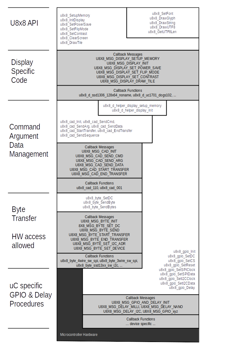
Agreed, for U8g2 pin numbers must be provided from extern (either via constructor or by writing your own callback functions). No other assumption is done on pin numbers. Infact this also makes the architecture of u8g2 a little bit complicated. The picture below shows the architecture starting at u8x8 API level (u8g2 is build on top of the u8x8 API) down to the Arduino Core library access.
Howdy, There is support for ESP32 in the Arduino IDE on Linux. See:
https://github.com/espressif/arduino-esp32
Did I mis-understand some deeper story?
I tried sometime back, but I failed due to the missing package description (json file). Is this available meanwhile? I guess i need to give it a try...
I do my unit testing on Arduino IDE on Linux (Ubuntu) so will be delighted to assist you getting it up and running. I'm at your disposal. Quickest/easiest way (for me) is that when you are ready and have a Linux shell prompt/UI in front of you, ping me on skype (neil.kolban) and you can share your screen and I'll walk you through the steps (if needed). Shouldn't take 15 minutes.
Nice offer, jet my hope was, that i can just fetch ESP32 Support from the Ardunio Board Manager. Is this possible meanwhile? Btw, I have UTC+2 here...
I don't believe the Board Manager technology can be used to install the ESP32 support for the Arduino IDE. I have always followed the instructions found here:
https://github.com/espressif/arduino-esp32#installation-instructions
I have tested both Windows and Linux instructions and they have both worked for me. I'm in UTC-6. Our best hope for availability overlap will likely be weekend.
ok, looks like the install instructions became more simpler compared to my last visit. Nevertheless also the json package file for the board manager seems to be on the way.
I am not sure, when i find some time to work on this. U8g2 is not working at all for ESP32? What are the major problems you face with U8g2 on ESP32? How does SPI.begin() behave on an ESP32? Are there any default "SPI" ports for the Arduino simulation?
Some good news here: I have EPS32 support within Arduino IDE working. I also successfully connected my Sparkfun ESP32 Thing.
U8g2 works without problem, but HW I2C pinremapping was not supported until now, so this was the first improvement what I did:
U8G2_SSD1306_128X64_NONAME_1_SW_I2C u8g2(U8G2_R0, /* clock=*/ 16, /* data=*/ 17, /* reset=*/ U8X8_PIN_NONE); // ESP32 Thing, pure SW emulated I2C
U8G2_SSD1306_128X64_NONAME_1_HW_I2C u8g2(U8G2_R0, /* reset=*/ U8X8_PIN_NONE, /* clock=*/ 16, /* data=*/ 17); // ESP32 Thing, HW I2C with pin remapping
Pin remapping triples time compared to digitalWrite/SW I2C bit banging:
U8G2_SSD1306_128X64_NONAME_1_SW_I2C EPS32 Clip=9.5 Box=9.6 @=8.9 Pix=9.1
U8G2_SSD1306_128X64_NONAME_1_HW_I2C EPS32 Clip=30.5 Box=31.3 @=24.7 Pix=26.7
It is especially useful on boards with 2 or more SPI modules such as on the ESP32. I probed around with a scope and found out that the constructor selects VSPI as opposed to HSPI module.
I started to investigate the Arduino Libraries for the ESP32: There is no support for HSPI at the moment: See ~/Arduino/hardware/espressif/esp32/libraries/SPI/src/SPI.c It would require an extension of the existing board support software to support both SPI channels.
@neilpanchal Do you still require the pin remapping feature for SPI? It can be implemented only for VSPI. Moreover, it will only remap CLK and MOSI. MISO will stay at default position.
Update: For HSPI support, an additional line
SPIClass SPI1(VSPI);
is required at the end of ~/Arduino/hardware/espressif/esp32/libraries/SPI/src/SPI.c
One additional line
extern SPIClass SPI1;
is required for ~/Arduino/hardware/espressif/esp32/libraries/SPI/src/SPI.h
EDIT: For HSPI support, an additional line
SPIClass SPI1(HSPI);
is required (typing mistake in my above statement)
I have created a beta release: https://github.com/olikraus/U8g2_Arduino/archive/master.zip Install this zip file via the Arduino IDE add zip file menu of the library manager.
@olikraus @nkolban I am going to try to see if I can get it working on HSPI lines. The culprit might be this line in SPI.cpp:
SPIClass SPI(VSPI);
I made a typing mistake. The additional required line is:
SPIClass SPI1(HSPI);
Additional comment: I just had a discussion here #378 about ESP8266. It looks like they have removed the flexible pin assignment via SPI.begin() statement (instead they have added an extra statement for this). The point is this: This request is related to a none-standard ESP32-specific extension for SPI library, which might change at any time in future, breaking u8g2 library for ESP32. Exactly this has happend now with ESP8266.
Update: I was wrong, the ESP8266 SPI lib has not been changed, but the ESP8266 as a complete different way to specify other pins for the SPI interface compared to ESP32. This means ESP8266 and ESP32 do not have the same interface for specifing the SPI pins.
SPI Lib ESP8266: Link: https://github.com/esp8266/Arduino/blob/master/libraries/SPI/SPI.h#L56 Uses "pins" member function to assign movable pins: pins(int8_t sck, int8_t miso, int8_t mosi, int8_t ss); Note, that ss and mosi are required areguments
SPI Lib ESP32: Link: https://github.com/espressif/arduino-esp32/blob/master/libraries/SPI/src/SPI.h#L55 The begin() member function accepts several (optional) arguments for the assignment of the pin numbers: "void begin(int8_t sck=SCK, int8_t miso=MISO, int8_t mosi=MOSI, int8_t ss=-1);"
Wire Lib ESP8266 Link: https://github.com/esp8266/Arduino/blob/master/libraries/Wire/Wire.h#L53 Has a "pins" member function which is declared as deprecated. "pins(int sda, int scl)" Instead use "begin(int sda, int scl);"
Wire Lib ESP32 Link: https://github.com/espressif/arduino-esp32/blob/master/libraries/Wire/src/Wire.h#L55 The ESP32 Wire lib extends the begin() member function with optional pin arguments and also a frequency paramenter: "void begin(int sda=-1, int scl=-1, uint32_t frequency=100000);"
Conclusion:
Suggestions: ESP8266 and ESP32 should agree on common code regarding the extension for movable pins for SPI and Wire functionality.
From seeing the above differences my suggestion is to modify the ESP8266 project to make it compatible to the ESP32 project:
Update: Moved this topic to #381 as it is kind of unrelated to the SPI pinouts and VSPI/HSPI modules. @olikraus @nkolban
Thanks for investigating this. I am trying to validate the changes on my side but I've come across an interesting roadblock.
Arduino-esp32 dictates 4 ways of using the Arduino API with ESP-IDF in the instructions/readme.
One of those ways is to use Arduino API as an ESP-IDF component as described here. I managed to add Arduino API to ESP-IDF using this method. Next, I've added a component.mk file to @olikraus's U8g2_Arduino fork.
Component.mk has the following options to add source directors and include files:
COMPONENT_SRCDIRS:=src src/clib
COMPONENT_ADD_INCLUDEDIRS:=src src/clib
Now, U8g2 is a component of ESP-IDF and we can use the wonderful make menuconfig
utility that ships with ESP-IDF to add configuration parameters such as SPI ports or selection between VSPI & HSPI.
There is one problem. Usually, I am able to edit the SPI frequency in the u8x2_d_ssd1306_128x64_noname.c, however, no matter what frequency I set and upload to ESP32, I always get 8MHz as the clock freq. I've validated it using a scope.
Another way to use ESP-IDF + Arduino API is to leverage the Platform IO ESP32 framework. So, I tried the same test as above and I changed the u8x8_d_ssd1306_128x64_noname.c LINE 235
to use 10 MHz as the clock frequency. This time, using Platform IO toolchain, it works! I checked it with a scope and I am getting 10 MHz as the clock frequency.
I am pretty sure I am missing something obvious here.
Any ideas on what must be going on? Any chances I make to the u8x8_d_ssd1306_128x64_noname.c
using Method 1 gets ignored when I compile the source. Method 2 works flawlessly and I can get a much better performance by tweaking the u8x8_d_ssd1306_128x64_noname.c
@olikraus
I have created a beta release: https://github.com/olikraus/U8g2_Arduino/archive/master.zip Install this zip file via the Arduino IDE add zip file menu of the library manager.
I don't use Arduino IDE so I unzipped the file and added as a component to ESP IDF using component.mk.
Then I added I am getting the following error:
SPIClass SPI(VSPI);
SPIClass SPI1(HSPI);
at the end of SPI.cpp
in Arduino-ESP32 component and also
extern SPIClass SPI;
extern SPIClass SPI1;
at the end of SPI.h
file.
I am getting the following error when running make flash
.
In file included from /home/neil/esp/esp-idf/components/driver/include/driver/spi_common.h:22:0,
from /home/neil/esp/esp-idf/components/driver/include/driver/spi_master.h:23,
from /home/neil/esp/esp-idf/components/driver/include/driver/sdspi_host.h:22,
from /home/neil/esp/esp-idf/components/fatfs/src/esp_vfs_fat.h:21,
from /home/neil/esp/projects/tutorials/arduino-test/components/arduino/libraries/SD/src//sd_diskio.cpp:20:
/home/neil/esp/esp-idf/components/soc/esp32/include/soc/spi_struct.h:678:18: error: conflicting declaration 'spi_dev_t SPI1'
extern spi_dev_t SPI1;
^
In file included from /home/neil/esp/projects/tutorials/arduino-test/components/arduino/libraries/SD/src//sd_diskio.h:18:0,
from /home/neil/esp/projects/tutorials/arduino-test/components/arduino/libraries/SD/src//sd_diskio.cpp:14:
/home/neil/esp/projects/tutorials/arduino-test/components/arduino/libraries/SPI/src/SPI.h:84:17: note: previous declaration as 'SPIClass SPI1'
extern SPIClass SPI1;
^
If I remove the modifications to SPI.h and SPI.cpp, make flash
is successful.
Looks like a conflict within ESP project. SPI1 is just a suggestion. It is used as secondary SPI device for other platfroms (like ATMega).
@olikraus Hi, I was able to get rid of the error. I've added the additional lines at the end of SPI.c and SPI.h.
SPIClass SPI(VSPI);
SPIClass SPIX(HSPI);
What is the procedure to now actually create a U8g2 class and specifying whether I want to use SPI
or SPIX
?
I opened an issue (https://github.com/espressif/arduino-esp32/issues/790) on esp32-arduino repo and the suggestion was to use the new SPI class. I am trying to now understand how does U8g2 create an SPI object in the library to initiate the communication.
Ok, I think I understand now. So the SPI instance is created within the esp32-arduino library and then adding the SPIClass SPIX(HSPI)
line creates another SPI instance with HSPI bus.
I found where I think the SPI instance is used in the u8x8lib.cpp file:
#if defined(ESP_PLATFORM) || defined(ARDUINO_ARCH_ESP32)
/* ESP32 has the following begin: SPI.begin(int8_t sck=SCK, int8_t miso=MISO, int8_t
* mosi=MOSI, int8_t ss=-1); */
/* not sure about ESP8266 */
if (u8x8->pins[U8X8_PIN_I2C_CLOCK] != U8X8_PIN_NONE &&
u8x8->pins[U8X8_PIN_I2C_DATA] != U8X8_PIN_NONE) {
/* SPI.begin(int8_t sck=SCK, int8_t miso=MISO, int8_t mosi=MOSI, int8_t ss=-1); */
/* actually MISO is not used, but what else could be used here??? */
SPI.begin(u8x8->pins[U8X8_PIN_I2C_CLOCK], MISO, u8x8->pins[U8X8_PIN_I2C_DATA]);
} else {
SPI.begin();
}
#else
SPI.begin();
#endif
I am going to try to see if I can pass the pointer to the new SPIX instance from the main.cpp and modify the u8g2 lib accordingly.
If the SPI object would be called SPI1 (instead of SPIX), you could use the U8g2 2nd SPI device: https://github.com/olikraus/u8g2/blob/master/cppsrc/U8x8lib.cpp#L460
Then, we need to activate the 2nd spi device: https://github.com/olikraus/u8g2/blob/master/cppsrc/U8x8lib.h#L88
Oh i just see, that there is an error. It should be SPI_INTERFACES_COUNT instead of WIRE_INTERFACES_COUNT
Hi @olikraus, I follow the discussion (and others more) with high attention! I am trying to interface an SD card (through SdFat library) and an MCP3208 SPI ADC. The board is a ESP32-WROOM-Module and for time purposes I want to use two separates SPI buses. I'd like to use HSPI for the SD card and VSPI for the ADC.
How did you solved you issue? I added the lines respectively on SPI.cpp and SPI.h:
SPIClass SPIadc(VSPI);
SPIClass SPIadc(HSPI);
extern SPIClass SPI;
extern SPIClass SPIadc;
But when I call SPIadc.begin(sck,miso,mosi,adc_cs) the ADC doesn't work, while If I use SPI.begin(sck,miso,mosi,adc_cs), everything works properly. Do you have some suggestions? Many thanks!
Unfortunately I can not say much about the ESP32 SPI implementation. I tested ESP32 once, and I think u8g2 should work in principle.
I have just tested a JLX12864G-08602 or JLX12864G-086, not marked which one. It is SPI and I checked that it could display Hello World (only top half, alas) using
U8G2_UC1701_MINI12864_1_4W_HW_SPI u8g2(U8G2_R0, /* cs=*/ 5, /* dc=*/ 4, /* reset=*/ 27);
Using HSPI at first did not work using:
U8G2_UC1701_MINI12864_1_2ND_4W_HW_SPI u8g2(U8G2_R0, /* cs=*/ 15, /* dc=*/ 4, /* reset=*/ 27);
After modifying the SPI.cpp and SPI.h including SPI1 as described by @neilpanchal, I modified U8x8lib.h:
`#if defined(ARDUINO_ARCH_ESP32)
/ define U8X8_HAVE_2ND_HW_SPI if the board has a second wire interface/ / As of writing this, I did not found any official board which supports this / / so this is not tested (May 2017), issue #224 / / fixed ifdef, #410, #377 / / meanwhile it is defined e.g. here: https://github.com/arduino/ArduinoCore-samd/blob/master/variants/mkrzero/variant.h#L91 / / so it should be available for mkrzero /
and the top half of Hello World showed again indicating that the HSPI is working.
Edit:
Doing additional testing using
U8G2_ST7565_JLX12864_F_2ND_4W_HW_SPI u8g2(U8G2_R2, /* cs=*/ 15, /* dc=*/ 4, /* reset=*/ 27);
and adding
u8g2.setContrast(128);
the text showed up correctly. Without changing the contrast, the screen was dark and the text could barely be seen.
Apparently the controller is not uc1701 as expected!
Looks like the modification for using the esp32 HSPI and u8g2 can be implemented just in U8x8lib.h and U8x8lib.cpp without modifying SPI.h and SPI.cpp. Still a kludge, but only 2 files to patch in the case of updates.
In U8x8lib.h, add this before #ifdef SPI_INTERFACES_COUNT:
extern SPIClass SPI1;
Edit: Oops, forgot to check in the u8x8lib.h before compiling. Does not compile using the extern SPIClass SPI1;
Only use:
and modify U8x8lib.cpp:
SPIClass SPI1(HSPI);
Only tested using Hello World, but a search for SPI1 in the u8g2 source files gave no result except in u8x8lib.*.
Hmmm....
Thank you @cbpdk !!! Your clean change made the trick neatly 🥇
I rephrased your change in this https://github.com/olikraus/u8g2/issues/1331#issuecomment-744720405
Hello, I send my request here cause it's linked to the solution proposed here. I'm trying the trick proposed by cbpdk above to set the hardware HSPI on my ESP32 WRover-E. Sadly it doesn't work in my case : Including u8g2lib.h make the controler loop before the setup part of my code. I removed everything and the issue is still there :
void setup(void) { Serial.begin(115200); // opens Console serial port Serial.println("Hello World"); }
void loop(void) { delay(100); }
The monitor shows : rst:0x1 (POWERON_RESET),boot:0x13 (SPI_FAST_FLASH_BOOT) configsip: 0, SPIWP:0xee clk_drv:0x00,q_drv:0x00,d_drv:0x00,cs0_drv:0x00,hd_drv:0x00,wp_drv:0x00 mode:DIO, clock div:1 load:0x3fff0018,len:4 load:0x3fff001c,len:1216 ho 0 tail 12 room 4 load:0x40078000,len:10944 load:0x40080400,len:6388 entry 0x400806b4 ets Jul 29 2019 12:21:46
rst:0x10 (RTCWDT_RTC_RESET),boot:0x13 (SPI_FAST_FLASH_BOOT) configsip: 0, SPIWP:0xee clk_drv:0x00,q_drv:0x00,d_drv:0x00,cs0_drv:0x00,hd_drv:0x00,wp_drv:0x00 mode:DIO, clock div:1 load:0x3fff0018,len:4 load:0x3fff001c,len:1216 ho 0 tail 12 room 4 load:0x40078000,len:10944 load:0x40080400,len:6388 entry 0x400806b4 ets Jul 29 2019 12:21:46
the RTCWDT_RTC_RESET is then repeated about every 8s. Can anyone help me solve this ? The library is really nice and works well in SW but I need to have it run in HW mode with HSPI. Thank you.
Looks like an issue with some Real Time Controller (RTC) Watch Dog Timeout (WDT). From my perspective this has nothing todo with u8g2.
Thank you for your answer Olikraus.
It's possible, I don't use Watchdog. But the same code without #include
Using u8g2 procedures may cause and additional delay which then may cause the RTC watch dog timer to reach its timeout. I do not know much about ESP, but maybe the RTC WDT was enabled once in history and now causes issues with your current sketch: I mean the RTC WDT setup might have survived the flash operation and is still active, so you think it is caused by u8g2 but the root cause is a real time clock related script, which you have used long back in history (which is still partly active). Did you try something related to any RTC? I have also seen related issues with the lib itself: https://github.com/espressif/esp-idf/issues/8184
Sorry to distrub you @olikraus. It seems the issue comes from my esp32 with SPIClass : I've got the same behavior with SPIClass SPI1(HSPI) (or VSPI) in the declarative zone, but it works fine when it is in the program. Thank you for your help, I'll investigate on this and send what I found here.
Hello. I got it ! I renamed in u8x8lib.cpp I renamed all the SPI1 to secondSPI and it works fine. Once again @olikraus, thank you for your help.
Thanks for the feedback. Maybe this is also useful for others.
A short follow up.
Since I first made the modification for using SPI1, I have not tested it until now.
Before recompiling and loading a new image, it was verified that it was still displaying the text.
Recompiling the original project with the current versions of Arduino-Esp32 and U8g2, it does behave as described by @FRed49300.
Renaming SPI1 to secondSPI as described got rid of the WDT reboot,
but the JLX12864G-08602/JLX12864G-086 display remains blank, using:
U8G2_ST7565_JLX12864_F_2ND_4W_HW_SPI u8g2(U8G2_R2, /* cs=*/ 25, /* dc=*/ 33, /* reset=*/ 32);
Switching to SPI using:
U8G2_ST7565_JLX12864_F_4W_SW_SPI u8g2(U8G2_R0, /* clock=*/ 18, /* data=*/ 23, /* cs=*/ 25, /* dc=*/ 33, /* reset=*/ 32);
it does work, but a lower contrast setting is required, around 50 in place of 128 or more. The higher contrast numbers black out the display.
The SD Card seems to work using SPI1 (HSPI) solving the problem using the display together with a SD Card.
Hmmm the contrast should be independent from the communication layer.
@ cbpdk @olikraus I encountered the same problem. When using stm32F401, it is also JLX12864G-08602/JLX12864G-086 display, which can be displayed, but the front is blank. I set various contrast and voltage parameters, and the result is the same. The pixels are all filled. Look at my code.
void uc1701x_init(void) { u8g2_Setup_uc1701_mini12864_f(&u8g2, U8G2_R0, u8x8_byte_4wire_hw_spi, u8x8_stm32_gpio_and_delay); u8g2_InitDisplay(&u8g2); u8g2_SetPowerSave(&u8g2, 0); }
//设置屏幕spi引脚和延迿 uint8_t u8x8_stm32_gpio_and_delay(U8X8_UNUSED u8x8_t u8x8,U8X8_UNUSED uint8_t msg, U8X8_UNUSED uint8_t arg_int,U8X8_UNUSED void arg_ptr) { switch (msg) { case U8X8_MSG_GPIO_AND_DELAY_INIT: HAL_Delay(1); break; case U8X8_MSG_DELAY_MILLI: HAL_Delay(arg_int); break; case U8X8_MSG_GPIO_DC: HAL_GPIO_WritePin(RS_GPIO_Port, RS_Pin, (GPIO_PinState)arg_int); break; case U8X8_MSG_GPIO_RESET: HAL_GPIO_WritePin(RESET_GPIO_Port, RESET_Pin, (GPIO_PinState)arg_int); break; } return 1; } //设置屏幕spi发鿁数捿 uint8_t u8x8_byte_4wire_hw_spi(u8x8_t u8x8, uint8_t msg, uint8_t arg_int,void arg_ptr) { switch (msg) { case U8X8_MSG_BYTE_SEND: HAL_SPI_Transmit(&hspi1, (uint8_t *) arg_ptr, arg_int, 10000); break; case U8X8_MSG_BYTE_INIT: break; case U8X8_MSG_BYTE_SET_DC: HAL_GPIO_WritePin(RS_GPIO_Port, RS_Pin, (GPIO_PinState)arg_int); break; case U8X8_MSG_BYTE_START_TRANSFER: HAL_GPIO_WritePin(CS_GPIO_Port, CS_Pin, GPIO_PIN_RESET); asm("nop"); // 1/x MHz us break; case U8X8_MSG_BYTE_END_TRANSFER: asm("nop"); // 1/x MHz us HAL_GPIO_WritePin(CS_GPIO_Port, CS_Pin, GPIO_PIN_SET); break; default: return 0; } return 1; }
@olikraus found that after commenting out this item, it can be displayed normally, but the contrast cannot be adjusted. I suspect that the SPI setting and contrast are not well matched. I use hardware SPI.
case U8X8_MSG_DISPLAY_SET_CONTRAST:
u8x8_cad_StartTransfer(u8x8);
//u8x8_cad_SendCmd(u8x8, 0x081 );
//u8x8_cad_SendArg(u8x8, arg_int >> 2 ); /* uc1701 has range from 0 to 63 */
u8x8_cad_EndTransfer(u8x8);
break;
@olikraus Run to stm32f4xx hal At spi. c, the transmitted data is 1, and the contrast changes.
/ Transmit data in 8 Bit mode / else { if ((hspi->Init.Mode == SPI_MODE_SLAVE) || (initial_TxXferCount == 0x01U)) { ((__IO uint8_t )&hspi->Instance->DR) = (*hspi->pTxBuffPtr); hspi->pTxBuffPtr += sizeof(uint8_t); hspi->TxXferCount--; }
I am not exactly sure, what the problem had been, but I am happy, that you found a solution.
I've been dealing with a perplexing issue with U8G2 and custom SPI pins on an ESP32-S3. It really is quite bizarre...I'm trying to figure out what in the world is going on!
I'm using U8G2 with an SSD1309-based 128x64 OLED panel. It is worth noting that everything works perfectly fine with appropriate bit-banged "SW_SPI" constructor (if a little slow), with the following constructor defined:
//U8G2_SSD1309_128X64_NONAME2_F_4W_SW_SPI u8g2(U8G2_R1, 40, 39, 47, 48); //SOFTWARE SPI
This proves that there is not a problem on the hardware level.
As there is not a constructor that provides the SPI pins, I did some digging around the source code. It turns out that the U8G2 source code has compiler #ifdefs for ESP32 and custom SPI pins--just there is no constructor provided to utilize this functionality. https://github.com/olikraus/u8g2/blob/3d41860b4308d60a920f56b65e1b01c155fdfe81/cppsrc/U8x8lib.cpp#L920-L935 (whoa...wait a minute...that's probably part of the problem! The lines use the I2C pin defs instead of the SPI pin defs! Bug alert! This error is also present in the "3wire_hw_spi" routine.)
Digging into the code a bit further, I found that the only difference between the "u8x8_SetPin_4Wire_SW_SPI" software SPI setup, and the "u8x8_SetPin_4Wire_HW_SPI" hardware SPI setup...was that the HW setup doesn't provide means for setting the CLK/DAT pin definitions. This is significant, because the above "setup routine" checks these pin definitions to determine whether or not to use the custom SPI pins in the hardware SPI setup. In short, there is no way to access the custom SPI pin setup functions.
Here is the software SPI pin definitions routine: https://github.com/olikraus/u8g2/blob/3d41860b4308d60a920f56b65e1b01c155fdfe81/cppsrc/U8x8lib.cpp#L1678-L1685
And the hardware SPI pin definitions routine: https://github.com/olikraus/u8g2/blob/3d41860b4308d60a920f56b65e1b01c155fdfe81/cppsrc/U8x8lib.cpp#L1734-L1739
Notice that literally the only difference is the omission of SPI_CLK and SPI_DATA on the HW_SPI routine. Armed with this info in mind, I created a custom constructor...to use the hardware SPI functionality, but simply use the SW_SPI pin definition call to also set the SPI_CLK and SPI_DATA pin lines. Should do the trick, right?
#include "U8x8lib.h"
#include "clib/u8g2.h"
// modified constructor to expose the clock/data pin fields...
class U8G2_SSD1309_128X64_NONAME2_F_4W_HW_SPI_CUST : public U8G2 {
public: U8G2_SSD1309_128X64_NONAME2_F_4W_HW_SPI_CUST(const u8g2_cb_t *rotation, uint8_t clock, uint8_t data, uint8_t cs, uint8_t dc, uint8_t reset = U8X8_PIN_NONE) : U8G2() {
u8g2_Setup_ssd1309_128x64_noname2_f(&u8g2, rotation, u8x8_byte_arduino_hw_spi, u8x8_gpio_and_delay_arduino);
u8x8_SetPin_4Wire_SW_SPI(getU8x8(), clock, data, cs, dc, reset); // YES, we're using the "SW" pin constructor. Only difference between "SW" and "HW" is that "HW" doesn't expose the rest of the pin setup fields
}
};
....well, turns out once I get PlatformIO's head screwed on correctly, the above code does work if the aforementioned bugfixes are made to the U8x8lib.cpp file. Spent a whole evening trying to get this working--only to find that PIO had made 2 copies of the U8G2 library. I was editing one, and PIO was compiling the other one--so of course nothing worked.
The next level is slightly beyond U8G2's scope, and that's to allow specifying of the MISO SPI pin. I understand and know that U8G2 does not read back from display modules--BUT in the interests of being able to share the SPI bus with other devices that WILL talk back...yeah, that is important. But like I said, not in U8G2's scope.
oooohhhhhh that seems to be a real bug... I will check further with #2123
The PR doesn't touch 3W SPI, so this is done with commit https://github.com/olikraus/u8g2/commit/9b20136f6e216f7e0d0539ea9d6c680bc9c3f86c
@WebDust21 and @kazetsukaimiko : Thanks a lot for your effort here. Excellent work.
@WebDust21 Thank you very much for the instructions on how to use custom HW-SPI pins on the ESP32 S3 !! After hours of searching this has finally helped me. 🙌
Hello,
U8G2_SSD1306_128X64_NONAME_F_4W_HW_SPI display1(U8G2_R0, /* cs=*/ 5, /* dc=*/ 2, /* reset=*/ 4);
Doesn't allow the user to define the MOSI and SCLK pins in the constructor.
It is especially useful on boards with 2 or more SPI modules such as on the ESP32. I probed around with a scope and found out that the constructor selects VSPI as opposed to HSPI module.
A couple of questions to try to understand the rationality behind protecting the user from defining the pins themselves.
Is it possible to connect displays on both HSPI and VSPI lines? I understand that I can use the chip-select (CS) pin to select between displays, however, I am trying to avoid robbing clock cycles and therefore reducing the framerate (not sure how true my claim is...but I just want to try it out).
I am curious why there are some drivers whose constructors allow for data and clock pin definition and others whose constructors don't. I am using SSD1306.
Is this something that needs to be handled by the ESP32 HAL? I haven't had a chance to delve into the U8G2 code, or the ESP32 IDF and/or espressif32 for Arduino.
Thank you!