 kevinfoley
commented
2 years ago
kevinfoley
commented
2 years ago Note: this code produces exactly the same bounding box. This was the first approach that popped into my head, but it's not the correct way to calculate AABB for a rotated entity.
m : mesh = e.get_mesh()
mesh_min = m.get_min_aabb_corner()
mesh_max = m.get_max_aabb_corner()

tf : transform  = e.get_transform()
aabb_min = tf.transform_point(mesh_min)
aabb_max = tf.transform_point(mesh_max)
center = ((aabb_max.x + aabb_min.x) /2, (aabb_max.y + aabb_min.y) /2,(aabb_max.z + aabb_min.z) /2)
I think the correct method is to calculate all 8 corners of the mesh bounding box, transform all 8, then get the min and max X, Y, and Z from those 8 transformed points.
 samueleruffino99
The axis-aligned bounding box (AABB) for an entity is not aligned correctly and does not fully encompass the entity if the entity is rotated.
Here, I have a gray cube that is rotated 45 degrees on each axis, and a transparent red cube used to visualize the AABB. Note that the AABB does not fully encompass the gray cube: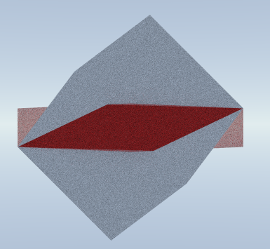
Script to generate the above image: