peterhinch / micropython_ir

Nonblocking device drivers to receive from IR remotes and for IR "blaster" apps.
MIT License
240 stars 51 forks source link

Bad Block with 2 Pi Pico W's on v1.22.1 uP #36

Closed jouellnyc closed 6 months ago

jouellnyc commented 6 months ago

Howdy.

I have 2 raspberry pi pico W's running:

MicroPython v1.22.1 on 2024-01-05; Raspberry Pi Pico W with RP2040 sitting a few inches away from each other.

Am able to run from ir_rx.test import test; test() on the the first and point a IR remote to it and get data back if I press "OK" or any button whatsoever:

i.e Data 0x40 Addr 0x0000 Ctrl 0x00

Life is very joyful...

Next, I take the second pi pico and an "Adafruit High Power Infrared LED Emitter - STEMMA JST PH 2mm" and perform:

from machine import Pin
from ir_tx.nec import NEC
nec = NEC(Pin(15, Pin.OUT, value = 0))
nec.transmit(0,1) 

(I've tried powering with 3.3 and 5.0 Volts - pin 36 and 40 respectively.) I have the proper stemma connectors and have DC power to the V+ power in, ground for ground, and then a 3-5V logic level signal on the input pin as per Adafruit.

I see the red led light up on the adafruit emitter and instantly I can see the the first/pico receiver reports back "Error: bad block".

If I use the acquire method, I get some data back for nec.transmit(0,1):

>>> from ir_rx.acquire import test
>>> test()
Waiting for IR data...
000  8949
001  7174
002  1837
003   550
004   578
005   527
006   607
007   553
008   579
009   552
010   578
011   553
012   579
013  1680
014   582
015  1684
016   581
017  1683
018   552
019  1711
020   550
021  1690
022   574
023  1685
024   579
025  1708
026  7657
027   526
028   922
029   394
030  1263
031   151
032   297
033   500
034   604
035   528
036   605
037   528
038   604
039   524
040   606
041   526
042   607
043  1683
044   581
045  1683
046   553
047  1707
048   555
049  1685
050   578
051  1684
052   552
053  1709
054   553
055  1712
056   549

Unknown protocol start 8949 7174 Burst length 57 duration 70952

[8949, 7174, 1837, 550, 578, 527, 607, 553, 579, 552, 578, 553, 579, 1680, 582, 1684, 581, 1683, 552, 1711, 550, 1690, 574, 1685, 579, 1708, 7657, 526, 922, 394, 1263, 151, 297, 500, 604, 528, 605, 528, 604, 524, 606, 526, 607, 1683, 581, 1683, 553, 1707, 555, 1685, 578, 1684, 552, 1709, 553, 1712, 549]

For fun, I've tried sending all sorts of values. (have tried researching the NEC protocol and read some issues in this repo but I figured the second pico should report something other than 'bad block? - I claim no expertise here...)

My goal is to just send 'any' data really via IR from the first pico to the other. Then once received I can do things like turn an led on/off or call up the President (j/k) or what have you.

Apologies for my lack of EE training, I hope it is clear.

Thanks for any guidance

peterhinch commented 6 months ago

The problem occurs at the start. The transmitter sends a ~9ms pulse correctly, but there should be a ~4.5ms gap: instead it's 7.174ms. After that it settles down and the pulse lengths are correct.

The stand-out feature of that Adafruit board is that it draws 400mA when on. This is very high: my suggested circuits draw about 50mA when on. My guess is that the long 9ms pulse is causing the power supply to droop and interfering with subsequent operation.

jouellnyc commented 6 months ago

Aha. Thanks very much @peterhinch. In my mind I thought the Adafruit board would 'just work'. Oh well. I suppose I shall take it up and retry your suggested circuit with the ir led as you mention and not so much the board..

Per their video, it seem like they were in fact looking to drive this pretty intensely for the sake of distance/etc...so sort of makes sense what we're seeing.

For fun/anyone interested, here are the 3.3 V output numbers (which per the Adafruit docs pushes 100 ma per led (200 ma for both):

from ir_rx.acquire import test test() Waiting for IR data... 000 8979 001 7278 002 521 003 104 004 185 005 472 006 552 007 582 008 551 009 582 010 547 011 559 012 574 013 556 014 573 015 582 016 580 017 1684 018 549 019 1685 020 579 021 1683 022 581 023 1685 024 551 025 1711 026 551 027 1686 028 581 029 1682 030 579 031 1741 032 7887 033 581 034 842 035 423 036 1365 037 202 038 220 039 473 040 551 041 554 042 582 043 550 044 580 045 551 046 579 047 1686 048 576 049 1685 050 552 051 1712 052 552 053 1684 054 580 055 1681 056 582 057 1660 058 573 059 1712 060 552

Unknown protocol start 8979 7278 Burst length 61 duration 72480

[8979, 7278, 521, 104, 185, 472, 552, 582, 551, 582, 547, 559, 574, 556, 573, 582, 580, 1684, 549, 1685, 579, 1683, 581, 1685, 551, 1711, 551, 1686, 581, 1682, 579, 1741, 7887, 581, 842, 423, 1365, 202, 220, 473, 551, 554, 582, 550, 580, 551, 579, 1686, 576, 1685, 552, 1712, 552, 1684, 580, 1681, 582, 1660, 573, 1712, 552]

Thanks again

peterhinch commented 6 months ago

USB A ports are supposed to be rated at 500mA, but many USB cables have significant resistance causing voltage drops. The 3.3V regulator on the Pico will also have a current limit - I don't know off the top of my head what this is.

The Adafruit board seems to be for "TV be gone" projects - people would walk into TV shops, operate the device, and every TV in the shop would turn off. A joke which surely passed its sell-by date at least a decade ago.

A 50mA drive seems plenty for normal remote control applications.

jouellnyc commented 6 months ago

When I was about 6 years old or so a salesman saw me watching a floor TV in a department store and hid behind the corner with the remote and turned it off. I turned and saw him smiling as if he was the best magician in the world...So I can see how TV be gone could be a popular item when it came out... Thanks again for the info @peterhinch

jouellnyc commented 6 months ago

This could just be anecdotal but, I tried the circuit here with a "Super-bright 5mm IR LED - 940 nm"

Was still getting bad block. Just to confirm I wasn't implementing incorrectly w/Emitter vs Collector, I tried it both ways :).

Also for fun I tried lowering R2 to 50 and 10 from 100 ohms. Same results. I hooked up a Multi meter connected in line with the IR led and got what appeared to be single digit milliamps. All along using an adafruit micro usb A cable.

The weird part, I think, was using 5V and aw/a 500 ohm resistor (I did not assume the laws of physics would be reversed just for me, it was more to see if I picked the right resistor or maybe it was mislabeled or some such things and let's just see what happens...) for R2, but acquire noted the protocol as NEC:

test() Waiting for IR data... 000 8959 001 6886 002 257 003 96 004 165 005 155 006 76 007 509 008 549 009 584 010 601 011 526 012 578 013 558 014 545 015 587 016 571 017 558 018 574 019 1690 020 575 021 1663 022 596 023 1666 024 600 025 1659 026 579 027 1740 028 7491 029 561 030 148 031 102 032 169 033 1895 034 235 035 102 036 291 037 1688 038 569 039 587 040 547 041 583 042 548 043 561 044 547 045 584 046 572 047 559 048 570 049 564 050 546 051 1714 052 548 053 609 054 522 055 1742 056 521 057 1712 058 551 059 1711 060 574 061 1691 062 523 063 1740 064 522 065 1718 066 546

NEC

[8959, 6886, 257, 96, 165, 155, 76, 509, 549, 584, 601, 526, 578, 558, 545, 587, 571, 558, 574, 1690, 575, 1663, 596, 1666, 600, 1659, 579, 1740, 7491, 561, 148, 102, 169, 1895, 235, 102, 291, 1688, 569, 587, 547, 583, 548, 561, 547, 584, 572, 559, 570, 564, 546, 1714, 548, 609, 522, 1742, 521, 1712, 551, 1711, 574, 1691, 523, 1740, 522, 1718, 546]

The from ir_rx.test import test; test() still yielded a bad block error however.

I'll likely try with an esp32 as well or maybe switch out to another pico, or keep swapping cable for a bit just to see what I can do...

peterhinch commented 6 months ago

I'm baffled. Have you tried acquire with your NEC remote to check that the receiver gets the right start sequence? [EDIT] This is the waveform on pin 17 of a Pico at the start of an NEC transfer (using the same code as you, except that my PCB uses pin 17). Image 
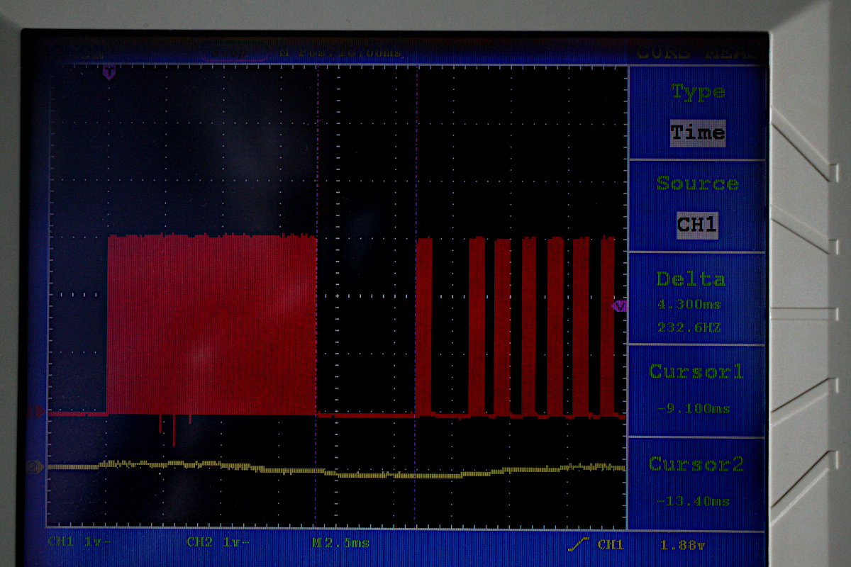
note the 9ms burst followed by a 4.3ms gap

jouellnyc commented 6 months ago

Yes, this is the output from the hand held remote hitting the 'ok' button

test() Waiting for IR data... 000 9065 001 4437 002 641 003 496 004 638 005 523 006 610 007 520 008 613 009 498 010 636 011 523 012 611 013 520 014 612 015 525 016 611 017 523 018 611 019 1629 020 610 021 1629 022 613 023 1631 024 612 025 1628 026 610 027 1630 028 612 029 1607 030 636 031 1628 032 609 033 1631 034 613 035 523 036 609 037 496 038 638 039 1631 040 610 041 1629 042 613 043 1629 044 610 045 500 046 632 047 503 048 633 049 523 050 610 051 1634 052 624 053 1614 054 611 055 523 056 610 057 499 058 638 059 497 060 633 061 1631 062 611 063 1631 064 615 065 1630 066 609

NEC

[9065, 4437, 641, 496, 638, 523, 610, 520, 613, 498, 636, 523, 611, 520, 612, 525, 611, 523, 611, 1629, 610, 1629, 613, 1631, 612, 1628, 610, 1630, 612, 1607, 636, 1628, 609, 1631, 613, 523, 609, 496, 638, 1631, 610, 1629, 613, 1629, 610, 500, 632, 503, 633, 523, 610, 1634, 624, 1614, 611, 523, 610, 499, 638, 497, 633, 1631, 611, 1631, 615, 1630, 609]

It's got to be 'me' somehow. Although I have pretty methodically built up the circuit and tore it down many time w/various different resistors, replaced the IR LED with second new one, tested that the gpio can turn on a simple led, and tried the 2222 both ways...I think I was pretty diligent. Perhaps it's time for a run with an esp32, but it seems you've got it work w/a pico.

I can't consistently repro this at the moment however. The only really consistent thing is what appears on the multi meter as a very low current (mostly low to much less then single digit milliamps)

peterhinch commented 6 months ago

OK, you've definitely proved that the fault is with the transmitter.

The Pico transmitter uses the PIO and has been extensively tested. While it's impossible to definitively rule out a bug, the above scope trace does illustrate a correct start sequence. The balance of probability is that there is something wrong with your setup, but you have clearly been pretty thorough in your testing.

It's worth noting that it's not just the start sequence that is wrong: in the last printout with your transmitter, there are other anomalies such as:

030 148 031 102 032 169

Clutching at straws, have you tried a different power source and cable? You might consider posting a photo of your setup in case I can spot something.

jouellnyc commented 6 months ago

Thank very much @peterhinch , Yes I have swapped usb cables - I have a stack of 'known good' usb cables that make my esp32s and picos happy... I appear to be getting 4.84 V from the PC - I have both picos through a mini hub - I went as far as adding a magnifying glass w/light at the same time on the hub and pulled it on / off just to see if there's some variation on the V - I have been using this hub for a good while w/o any issues - but the 4.84 V seems stable:

PXL_20240211_150055760

But If I take the transmitter pico straight to the wall w/o hub I get 5.04 V - and If I put a little loop for transmit in main.py with a one second pause, I don't see anything on the receiver running acquire:

PXL_20240211_154409074

Here are a few angles of the circuit - I pulled the jumpers and used some flat wires to make it a bit easier to view:

PXL_20240211_152733215 PXL_20240211_152830670 PXL_20240211_152840969 PXL_20240211_152925351

For giggles, I have tried pin 17 but also have verified pin 15 can light a basic LED as well. I've used your repo before with good effects in a small project (with the EK8460 Receiver) but as of yet only with a "real" physical non-breadboard remote. https://github.com/jouellnyc/infrared_tag

Slightly unrelated perhaps, I saw many have trouble with pico to pico wireless as an AP/supplicant and I used espnow instead: https://github.com/jouellnyc/led_admin_console

My ambition here is merely fun - and some smiles on faces - It would be nice to get the IR working but I may go with esp32/esp32nows (have not yet hooked those up for the purposes of this setup just yet)

peterhinch commented 6 months ago

Hang on. You're saying

But If I take the transmitter pico straight to the wall w/o hub I get 5.04 V - and If I put a little loop for transmit in main.py with a one second pause, I don't see anything on the receiver running acquire.

You have a working test, but the receiver sees nothing after just changing the source of power? That make no sense at all. I would check whether your loop is actually running. Maybe substitute a visible LED and see if it flashes once per second.

Your pictures look fine. The difference in voltage (4.84/5.06) is immaterial because the Pico regulates it down to 3.3V for the chip. I'm completely foxed at the moment.

Re getting to Picos to communicate by WiFi, I haven't done any work on using them in AP mode. My efforts have been using MQTT where both are clients. In this mode they work fine.

jouellnyc commented 6 months ago

Firstly thanks for confirming my pics are valid and your insight with respect to the MQTT/etc.

In terms of the pico. in there lies my problem, I haven't had much to hang my hat on in terms of reproducible results. I also have a tendency to kick up dust in projects :).

Now, I had the same thought as you - I hooked up a red led in line but I moved over to the esp32 because I am not so sure about the pico ATM. That said, I can reliably produce the following consistently all day :)

This is what the pico pi receiver sees using an esp32 wroom as the transmitter:

1

MPY: soft reboot
Waiting for IR data...
000  8892
001  4547
002   488
003   613
004   516
005   587
006   573
007   561
008   527
009   627
010   493
011   616
012   515
013   612
014   518
015   597
016   539
017   586
018   517
019  1769
020   492
021  1747
022   518
023  1719
024   518
025  1720
026   517
027  1719
028   542
029  1721
030   543
031  1721
032   516
033  1720
034   539
035   589
036   496
037  1745
038   542
039   587
040   542
041   592
042   515
043   615
044   518
045   611
046   520
047   612
048   518
049   613
050   520
051  1720
052   515
053   614
054   566
055  1670
056   521
057  1744
058   516
059  1720
060   539
061  1730
062   514
063  1714
064   520
065  1747
066   511

NEC

2

MPY: soft reboot
Waiting for IR data...
000  8891
001  4519
002   511
003   613
004   526
005   606
006   520
007   561
008   569
009   559
010   545
011   638
012   518
013   613
014   497
015   560
016   567
017   591
018   516
019  1720
020   542
021  1720
022   515
023  1723
024   563
025  1701
026   515
027  1747
028   514
029  1723
030   542
031  1718
032   517
033  1694
034   545
035   611
036   548
037  1690
038   543
039   590
040   540
041   619
042   487
043   616
044   516
045   616
046   516
047   589
048   544
049   621
050   513
051  1717
052   513
053   604
054   530
055  1747
056   489
057  1747
058   515
059  1720
060   544
061  1721
062   511
063  1750
064   495
065  1768
066   490

NEC

And test now receives:

test() running Data 0x02 Addr 0x0000 Ctrl 0x00

once I send:

nec.transmit(0,2)

Voilia! I can send and receive.

The only thing I swapped out was the pico for the esp32 wroom and made (D4/GPIO4) on the wroom the source pin to drive the base of the 2222 and return the current to ground on it's GND pin as well as power the IR LED with it's VIN pin.

I have also rebooted both the pico and wroom - same joyful results -- :)

jouellnyc commented 6 months ago

To add on the above. I realize that this will sound odd but I can reliably now reproduce the following sequence of events:

I am not using different circuits, it's the same IR led, 2222, etc just swapping out the mc and rearranging the power/ground.

Action Outcome
Use esp32 wroom with red led in line Perfect signal to the Pico Receiver. Joy
Use esp32 wroom without red led in line No signal to the Pico Receiver
Different pi pico with red led in line Yes signal to the Pico Receiver, but unknown protocol
Different pi pico without red led in line No signal to the Pico Receiver
Original pi pico with red led in line Yes signal to the Pico Receiver, but unknown protocol
Original pi pico without red led in line No signal to the Pico Receiver

Pico output with the red LED:

>>> from ir_rx.acquire import test
test()
Waiting for IR data...
000   654
001    80
002    94
003   110
004   172
005    75
006  7648
007  7298
008   623
009   104
010   445
011   105
012   493
013   621
014   493
015   614
016   540
017   668
018   493
019   589
020   491
021   664
022   489
023  1735
024   506
025  1823
026   414
027  1928
028   332
029  2004
030   286
031  1770
032   488
033  1780
034   461
035  1841
036   394
037  1881
038  7043
039   102
040   238
041   666
042   174
043   405
044   227
045   588
046   597
047  1589
048   173
049   104
050   126
051   753
052   248
053   909
054   438
055  1775
056   516
057   590
058   542
059  1744
060   442
061  1825
062   484
063  1755
064   516
065  1746
066   487
067  1823
068   414
069  1819
070   469

Unknown protocol start 654 80 Burst length 71 duration 72064

[654, 80, 94, 110, 172, 75, 7648, 7298, 623, 104, 445, 105, 493, 621, 493, 614, 540, 668, 493, 589, 491, 664, 489, 1735, 506, 1823, 414, 1928, 332, 2004, 286, 1770, 488, 1780, 461, 1841, 394, 1881, 7043, 102, 238, 666, 174, 405, 227, 588, 597, 1589, 173, 104, 126, 753, 248, 909, 438, 1775, 516, 590, 542, 1744, 442, 1825, 484, 1755, 516, 1746, 487, 1823, 414, 1819, 469]

I am happy to use the ESP32 with red led, so I feel I have a solution.

I am happy to try other things if it helps....

peterhinch commented 6 months ago

My last throw of the dice :) My test PCB's use standard Picos and it occurred to me that I'd never tested with a Pico W. So I did the following with a W:

  1. Installed firmware V1.22.1
  2. Installed IR TX using mpremote mip as per the doc.
  3. Edited main.py to read:
    from machine import Pin
    from ir_tx.nec import NEC
    from time import sleep
    while True:
    nec = NEC(Pin(15, Pin.OUT, value = 0))
    nec.transmit(1, 2)  # address == 1, data == 2
    sleep(1)
    print(".", end="")

    Finally I connected a logic analyser to GPIO15 and connected the Pico W to a power source. This was the outcome: Image If you click on the image you will see some measurements which show that the timings are correct. I also checked the carrier frequency which the LA reported as 38.02KHz.

I'm stumped. The driver passes every test I can throw at it, your setup looks fine, yet clearly something is wrong. Short of turning up on your doorstep with a bunch of test gear I've run out of suggestions. If you can get access to an oscilloscope I'd have a close look at the power supply but short of that I think you'll just have to go with what works: ESP32.

The reason I mention power again is this. We're using the same hardware with the same firmware, and running the same code. As far as I can see, the only difference is the source of power.

jouellnyc commented 6 months ago

I hear that. To bring this to a bit of a close (time lapsed over a few hours):

So I now have evidence of a pico H working.

So I now have evidence of a pico W working.

Basic empirical evidence points to "local problems" in my setup and the 1000 ohm resistor but that one worked with the esp32. That was a quality resistor - never had any problems from that batch / vendor. (After testing below, I confirmed this 1000 R actually worked just fine placing it in another circuit).

However, two thing I did notice:

Summary:

NOTE: I don't claim any of this as authoritative - it was just my experience with a mix of run of the mill electronics. (no access to an oscilloscope)

Thank you very much @peterhinch for all of your help. I hope some of this information can help others with this excellent repo.

Some payoff pics:

th

https://github.com/peterhinch/micropython_ir/assets/32470508/ecc7bd4e-2de1-4d78-b1e8-568daa7141d5

peterhinch commented 6 months ago

I'll close this as complete, but to add a couple of general points:

  1. Electronic components are generally extremely reliable. In nearly 60 years of working with them I don't think I ever encountered a duff resistor (aside from ones that had been "blown up"). The one exception is capacitors which can fail after long periods.
  2. The IR transmitters and receivers have limited active angles: to achieve decent range the transmitter and the receiver need to be pointing at each other.
jouellnyc commented 6 months ago

Thanks again @peterhinch - your help and experience here is very much appreciated. Good note about the angles as well.