pimoroni / pimoroni-pico

Libraries and examples to support Pimoroni Pico add-ons in C++ and MicroPython.
https://shop.pimoroni.com/collections/pico
MIT License
1.3k stars 493 forks source link

Interstate75 - supporting more panel types #233

Open WattsC-90 opened 2 years ago

WattsC-90 commented 2 years ago

Hi, I have been playing with the new Interstate 75 and some LED panels I got off AliExpress. It seems like the boards I have (32x16 and 64x32) use differing drivers than are supported by the native hub75 code.

I cannot tell what the General PanelType supports, but it doesnt seem to work (trying to light 8 rows lights 16 and lighting 1 led will end up with 2 leds lit 8 rows apart). But I have determined that the drivers in use on my boards are the SM16017 and the DP5020B. I have the datasheets if someone can figure it out? I am assuming its a timing thing to do with the OE/LE/(rowselect) pins? but its been a while since I have had to be this involved in hardware.. I would love to be able to contribute to the library itself to know how I can add drivers etc? looking at the code I can see how its possible but not clear on what the current library supports!

DP5020B-DP.zh-CN.en.pdf SM16017-ShenzhenSunmoonMicroelectronics.zh-CN.en.pdf

Images:

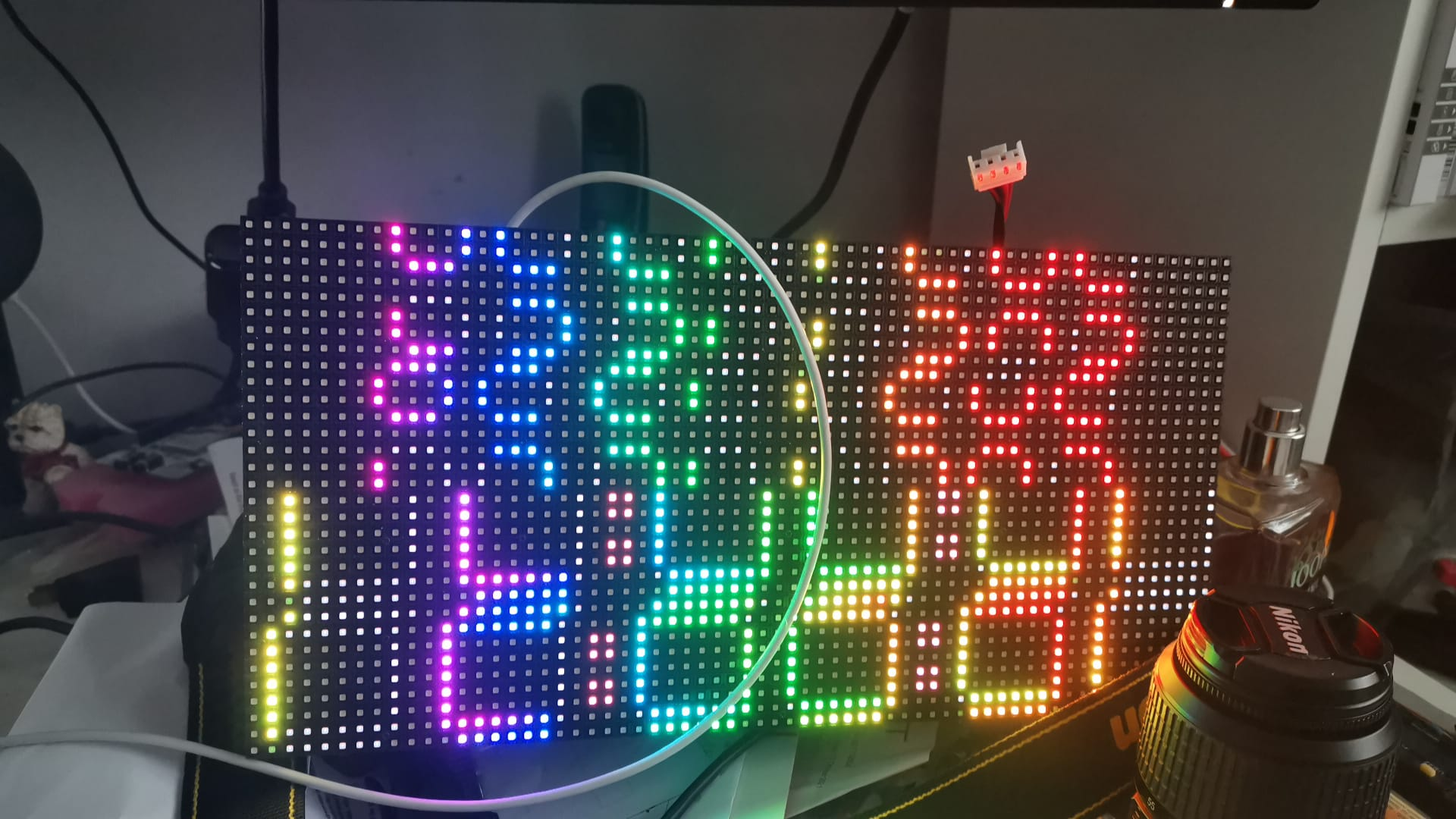
Notice the indented odd rows image

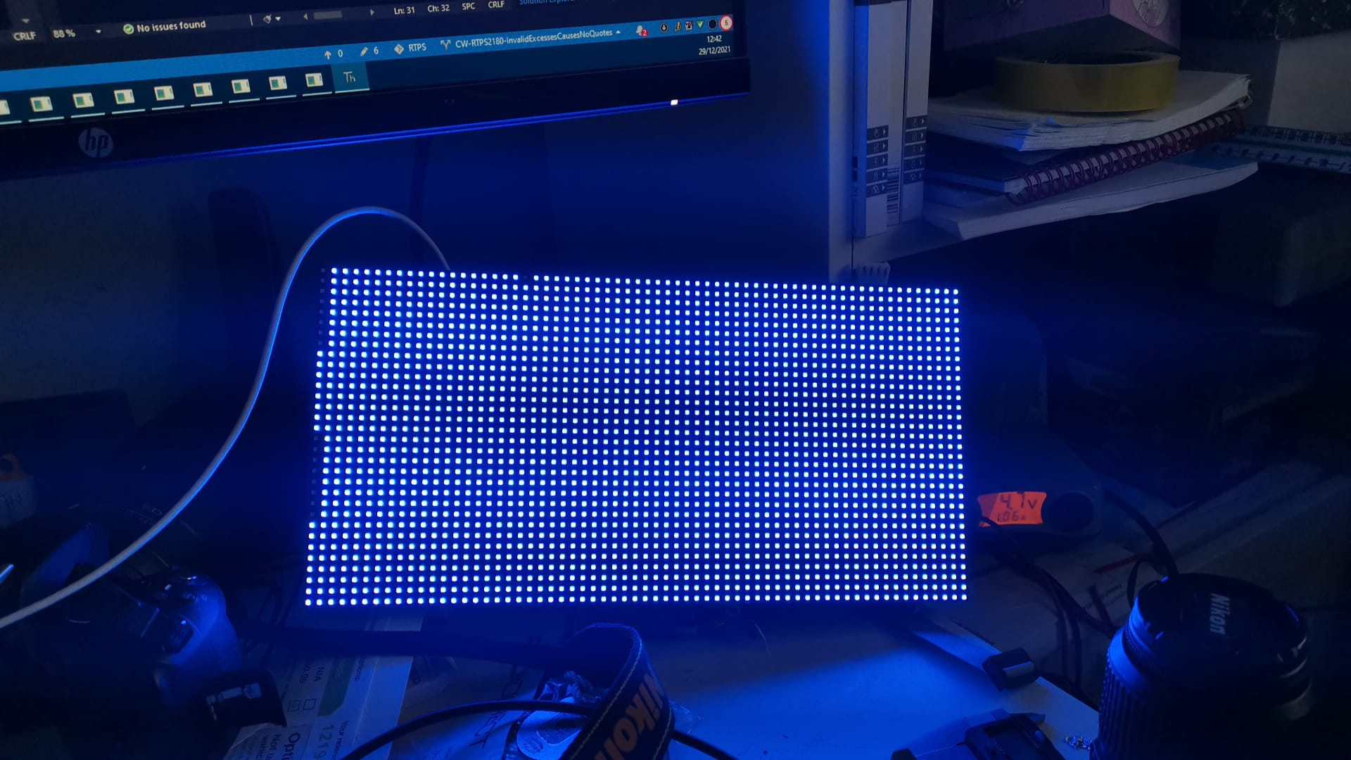
In this code, I have lit pixel 5,5 to be red (255,0,0), but 2 pixels are lit. the code:

import hub75

WIDTH = 64
HEIGHT = 64

matrix = hub75.Hub75(WIDTH, HEIGHT)

matrix.start()
matrix.clear()
matrix.set_rgb(5, 5, 255, 0, 0)
matrix.flip()

image

Just to highlight the issue, this is the clock demo code from the repo: image

Gadgetoid commented 2 years ago

The first thing to try would be inverting the strobe pin, which is given as an option "stb_invert", eg:

hub = hub75.Hub75(WIDTH, HEIGHT, stb_invert=True)

The panel driver code is split between some very dense and unfriendly PIO programs and the C++ glue that holds it all together. It's not very malleable.

Your first port of call- I suppose - would be to check that the Latch, Strobe and Output Enable pin polarities of your panels match those used in the library.

The second possibility would be the LED routing. Knowing the details of the driver ICs is only one piece of the puzzle. If your panel LEDs are routed in a snake pattern, interleaved, or some other weirdness it would require some fundamental changes to the library to support.

It might make sense to drop PIO and go back to some bare C++ or Python examples driving the panels slowly but carefully to figure out how they're supposed to work and build from there.

I wrote the HUB75 C++ example just to get my head around our panels so I could put together the library- see this unrolled code here: https://github.com/pimoroni/pimoroni-pico/blob/main/examples/interstate75/interstate75_hello_world.cpp

PlatinumFusion commented 2 years ago

I have a similar issue, but when using the SmartMatix with the Teensy, I had change the mapping. I wonder if it just needs to be remapped?

Gadgetoid commented 2 years ago

@WattsC-90 have any luck getting it up and running? Could you grab a photo of the input connector on the back, specially if there are some pinout labels there. @PlatinumFusion’s thoughts about mapping made me wonder if the connector has a different pinout, which may also explain this.

Support for alternate pinouts may be possible. Alternate LED layout mappings might be quite a bit trickier.

WattsC-90 commented 2 years ago

@Gadgetoid no never got this up and running, i was debating just buying the pimoroni panels and saving myself a lot of leg work.. but its a cost vs time issue.. (both of which I have none at the moment 😭) I have struggled to get schematics off the supplier of the boards so not sure how to progress anyway.

I have been trying to figure out the MAXIMUM panel size for the interstate though using the pimoroni boards, i wonder if thats a stat you have?

brunnelu commented 2 years ago

I think the problem has to do with the additional garbage value sent to finish a line in the pio https://github.com/pimoroni/pimoroni-pico/blob/main/drivers/hub75/hub75.pio

.wrap ; Note that because the clock edge for pixel n is in the middle of pixel n + ; 1, a dummy pixel at the end is required to clock the last piece of genuine ; data. (Also 1 pixel of garbage is clocked out at the start, but this is ; harmless) Maybe I can figure it out

Stubbs commented 2 years ago

I wonder if the issue here could be the scan rate of the panels. Outdoor types tend to be 1/8 scan while indoor ones (which are the more common) tend to be 1/16. I know my panels are 1/8s and I get a clock that looks very similar to the 3rd photo, but all in red.

brunnelu commented 2 years ago

Depending on the display it can be both. I found that the extra pixel can be a problem at least on my panels. Also I do have some 1/8 scan matrices (32 height) and 1/4 scan (16 height) -> 4 scan rows each. Even though one could transform the coordinates. I found way to many options. I have some panels, where one has to invert some blocks, ...

Depending on the panel. If it is possible try to half the rows and double the columns. If the matrix can be lit completely you are lucky and you can write a wrapper for set_color to transform pixel coordinates.

Stubbs commented 2 years ago

The matrix is 64x32, so by setting the width & height to 128x16 I do manage to full the display lit (only in red funilly enough, green & blue don't work)

It fills the screen in 8 chunks, starting from 0,16, going to 16,16 followed by 0,8 to 16,8 then 0,31 to 16,31 and so on.

This is the code I've used ...

import hub75
import time

WIDTH = 128
HEIGHT = 16
C = 8

matrix = hub75.Hub75(WIDTH, HEIGHT)

matrix.start()
matrix.clear()

for x in range(WIDTH):
    for y in range(HEIGHT):
        matrix.set_rgb(x, y, 255, 255, 255)
        matrix.flip()