 LorenzMeier
commented
8 years ago
LorenzMeier
commented
8 years ago @tumbili I'm going to fix this for our internal use with a couple of these: https://www.sparkfun.com/products/11955
Open LorenzMeier opened 8 years ago
LorenzMeier
commented
8 years ago @tumbili I'm going to fix this for our internal use with a couple of these: https://www.sparkfun.com/products/11955
LorenzMeier
commented
8 years ago @AndreasAntener @SimonWilks FYI: You can have a few of the ones I'm ordering if you need them.
@tridge FYI: You will want to retrofit your planes with this. I've notified 3DR / HK and other HW manufacturers that the design is flawed. The setup on Pixhawk turns out to be marginal (it kind of works) but any deviation (higher supply voltage, longer cable runs, noise) can turn it from OK to unreliable.
LorenzMeier
commented
8 years ago Note that I2C is different from UART and other interfaces which apply TTL levels (so < 0.8V is off, > 2.5V is on). For I2C < 30% of VCC is off, > 70% VCC is on. Which means that the ON voltage is 3.5V at 5V supply, making 3.3V just marginal.
 pkocmoud
commented
8 years ago
pkocmoud
commented
8 years ago We will have a new airspeed design that include a proper level shifter on board and JST GH connectivity. We also have an i2c hub design based on the PCA9516A which will accept either 3.3v or 5v i2c on each of 4 ports.
 proficnc
commented
8 years ago
proficnc
commented
8 years ago the correct fix here is to have an LDO on the Airspeed sensor.
running 3.3V around is really bad.
this is what we do in the GPS. it allows for some noise in the power line, without affecting the system stability.
There is no need for a level shifter here. just follow the correct power setup.
proficnc
commented
8 years ago ok, so it appears that there may be more going on here. I have a board with the 3.3v version and another with the 5V version.
to retrofit the 5V version... then use the level shifter, to retrofit the 3.3v version, use an LDO... future designs should use the 3.3V version... and preferably a can interface.
 silkstone
commented
7 years ago
silkstone
commented
7 years ago @proficnc @LorenzMeier Hi guys, I am failing to get anything to come through the i2c port on my Pixracer - using an active i2c hub and connecting the PX4 digital airspeed sensor and a Ublox Neo-M8N GPS but have never been able to get a GPS lock and the airspeed sensor reads 0.0 with occasional spikes up to 50 m/s etc.
Tried following the conversation above but don't fully understand if this is the same issue that I am facing. Any help would be much appreciated!
pkocmoud
commented
7 years ago Have you calibrated your sensor?
 athertop
commented
7 years ago
athertop
commented
7 years ago How would one determine if a sensor is pixhawk compatible or not? I have the HK Pilot digital airspeed sensor connected to my pixhawk lite fc in a flying wing. It's about 4 months old. How can I tell if it's producing i2c errors?
pkocmoud
commented
7 years ago I would start by comparing the sensors model number to the sensors on existing known supported boards. If that is a match then proceed to study the pinout to ensure you are connecting it properly to the flight controller.
With the typical MS4525DO, I run "meas_airspeed info" from the NSH prompt. The i2c errors are listed there.
athertop
commented
7 years ago So there exists a list of supported sensors? As regards connections, the sensor does work, but after powering the craft (indoors) it sits at about 7km/h, and even if I do the pre-flight reset option it still goes to about 7km/h initially then slowly rises to upto 20km/h - in no wind (indoors). I have ordered a new sensor from auav to see if this will resolve, and have raised a case with HK.
pkocmoud
commented
7 years ago Are you using PX4 or ArduPilot?
athertop
commented
7 years ago Ardupilot Plane v3.7
pkocmoud
commented
7 years ago Have you posted anything on discuss.ardupilot.org? I think there is a way in Mission Planner to read the airspeed sensors status including Temp. I would expect there would be a correlation between the internal sensors temperature and the drift. Not sure why it starts so high though.
athertop
commented
7 years ago After reading this report here, I presumed it would be down to it being one of the sensors not supporting the 3.3v signal levels, and therefore getting i2c errors. Lorenz in here does mention that the sensors from HK do have this issue and that he reported it. I need to do the test you mention above. Need to figure out what the NSH prompt is :-) Is this one of the shells (cli's)available in MP (have used NutX shell before)?
pkocmoud
commented
7 years ago The issue listed here would cause the sensor to drop out or be missing. Drift is a fairly standard issue with these sensors. Some suggest a warm up period before use.
 dagar
commented
7 years ago
dagar
commented
7 years ago I don't think anything is reported over mavlink. On PX4 I'm adding complete logging for differential_pressure and airspeed which includes the driver error count. Internally you can look at the differential_pressure topic (listener differential_pressure 100).
pkocmoud
commented
7 years ago I have seen plotted Airspeed vs sensor temp from Ardupilot / Mission Planner that show this data.
dagar
commented
7 years ago Yes, there's airspeed and temperature, but not the driver error count. At that point the airspeed will also be filtered. Sorry should have been more specific.
 j07rdi
commented
7 years ago
j07rdi
commented
7 years ago Just to let you know guys we have been offering the airspeed with the fix since a few weeks ago: https://store.mrobotics.io/mRo-I2C-Airspeed-Sensor-JST-GH-p/mro-classy-arspd-mr.htm
 jliphard
commented
7 years ago
jliphard
commented
7 years ago @j07rdi - I bought two of your sensors, and for both of them I see a severe high frequency ripple on pin 2 (VCC) of the actual sensor, a MS4525. Due to ratiometric analog output, any problems with VCC will feed straight through into the output (pin 3), and from then on into the ADC.
1/ Could you please circulate a circuit diagram with some specs on what you were hoping for vis-a-vis the quality of your VCC?
2/ Correct me if i'm wrong, but after your LDO, (and whatever noise suppression elements you have in there) should VCC not be VERY smooth and within say +/- 1% of +5V? The sensor will sort of work, it will just be much noisier than you expected, and, more problematically, the temp compensation functionality internal to the MS4525 may not perform particularly well if VCC is all over the place.
3/ The expected pixhawk-level signature of this problem would be: (1) unexpectedly 'noisy' sensor readings with a periodicity to the noise, and (2) sensors whose thermal compensation is screwed, giving variable baselines that change from day to day. If you put up a circuit diagram, I can do a more detailed analysis of the PIX4AIRSPEEDv1.1 PCB.
pkocmoud
commented
7 years ago @jliphard - The sensor linked by @j07rdi uses the MS4525DO which is the i2c variant of the MS4525. I think you might be studying the wrong datasheet.
jliphard
commented
7 years ago Yes - that's it - you are right.
On Jun 22, 2017, at 4:48 AM, Phillip Kocmoud notifications@github.com wrote:
@jliphard - The sensor linked by @j07rdi is the MS4525DO which is the i2c variant of the MS4525. I think you might be studying the wrong datasheet.
— You are receiving this because you were mentioned. Reply to this email directly, view it on GitHub, or mute the thread.
 kaklik
commented
5 years ago
kaklik
commented
5 years ago Nevertheless, a circuit diagram of the @j07rdi linked sensor will be useful to verify a correctness of the design. The issue should not be closed until the explicitly known and verified design arise.
kaklik
commented
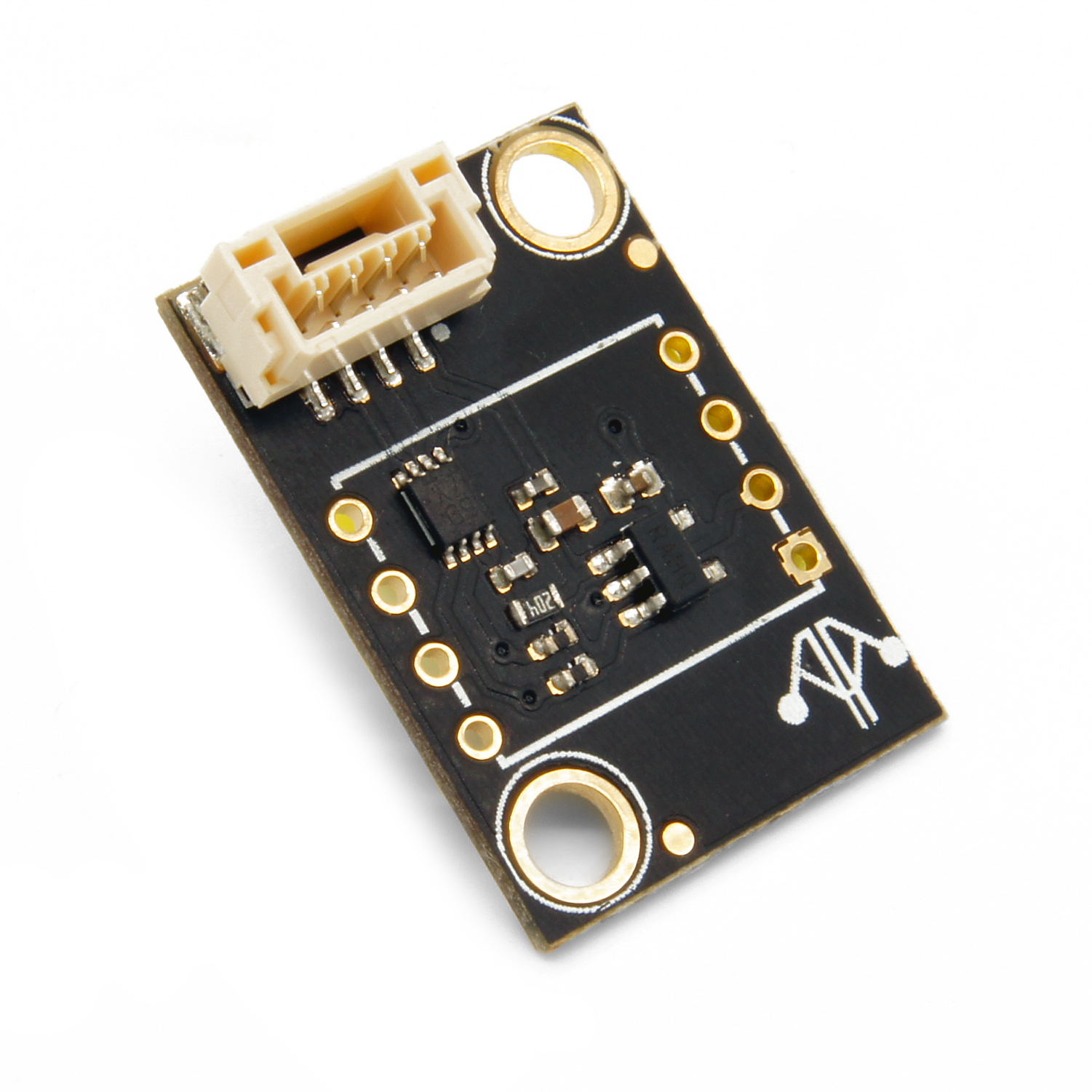
5 years ago @j07rdi Yes, I saw that promo picture. But it is not equivalent to schematics of level shifting circuit used.
Moreover, the picture contains unsoldered joints with not liquefied solder paste.

j07rdi
commented
5 years ago @kaklik
The huge chip on the upper part is the level shifter. Please grab a multimeter and verify the output voltages if there is any doubts.
Your observation is not accurate, the solder joins have soldering.
pkocmoud
commented
5 years ago @j07rdi - I think he would like the schematics updated to include the level shifting change.
The solder critique seems superfluous.
The PX4 airspeed sensor breakout is using a 5V sensor for a 3.3V bus, which is not compliant with the I2C spec and leads to thousands of read errors in a short time frame. It can be fixed in two ways:
Scope shots and further discussion here: https://github.com/PX4/Firmware/issues/3544#issuecomment-174732106