Closed verbessern closed 5 years ago
Go on. You could either plug the shield into a Uno and run the whole calibration sketch on the Uno.
Or just measure resistance with your DMM. This will determine the touch pins. Then run the calibration sketch on the ESP32 with the known XM, YP, XP, YM pins.
Make sure that XM, YP pins can be used for both Analog and Digital. XP, YM only need to be Digital.
David.
I don't have Uno. I never measured resistance, but it seems one wire from the DMM goes to ground other to the pin. Do you mean to make LOW one of the pins and measure the others, till i find which one changes when some pin is LOW?
Most shields use A1, A2, D6, D7 for the touch pins.
Unplug the shield. Measure the resistance between LCD_WR (A1) and LCD_D6, LCD_D7, LCD_D0, LCD_D1. i.e. one DMM probe on A1. place the other probe on D6, .... Then do the same with LCD_RS (A2).
You should find that you get about 300 ohms for one pair. And about 500 ohms for the other pair. Make notes of the results.
David.
Awesome! I found out that putting GPIO 14 LOW i can measure Y touch value on the display (by my orientation)! Great! I have to find now X and Pressure :).
What are the resistance values?
Yes that is true for the pins: WR, RS, D6, D7. But I'm getting very twisted space. Its not orthogonal and I will have to invert by a matrix. Is that normal? I see the examples of the calibration do linear interpolation.
The resistance i did not measure, because the wires are so many to reconnect, and the pins are already known.
Go on. Just say what the resistances are.
e.g. 345 ohms between LCD_WR and LCD_D7
e.g. 567 ohms between LCD_RS and LCD_D6
Also Lolin32 i think have 12 bit ADC and analogRead returns 0..4095, but the touchscreen.h for arduino that is used into the calibration code used 0..1023 so my results are even more twisted out of scale then usually.
I will ask once more.
Just say what the resistances are.
RS - D7 = 541 ohms WR - D6 = 610 ohms Fixed.
One question, what does XP, YP, XM, YM mean? I.e. what are this abbreviations?
I think i get it. The touch works by changing the resistance. Probably one pin is connected to top, one bottom, left, right and the 'magic' is putting electricity on one pin and measuring on the other how much is received. Awesome.
Ah...Plus and minus
Thank you very much for your help today @prenticedavid.
hello, I having a similar issue, I want to use the same screen with an esp32, display works well, but touch doesn't work. (it's not a problem on shield, it works well on Arduino uno)
if you succed using the display and touch with esp32, can you give me the wire you use and explain if you change Something on Library for pin mapping ?
thanks in advance.
i use this wiring :
define LCD_RD 2 //LED
define LCD_WR 4
define LCD_RS 15 //hard-wired to A2 (GPIO35)
define LCD_CS 33 //hard-wired to A3 (GPIO34)
define LCD_RST 32 //hard-wired to A4 (GPIO36)
define LCD_D0 12
define LCD_D1 13
define LCD_D2 26
define LCD_D3 25
define LCD_D4 17
define LCD_D5 16
define LCD_D6 27
define LCD_D7 14
and
int XP = 27, YP = 4, XM = 15, YM = 14;
i change touch pin to
int XP = 12, YP = 13, XM = 15, YM = 33;
it seems to work :)
but I really don't understand where pin are defined and I don't understand the logic with Arduino UNO pin (LCD pin vs TOUCH pin)
Your Shield appears to have
LCD_D0 XP
LCD_D1 YM
LCD_RS XM
LCD_CS YP
You could have plugged the shield into a Uno and the sketch would diagnose the pins.
An ARM or ESP32 can't diagnose. So you simply measure the resistance with a DMM.
David.
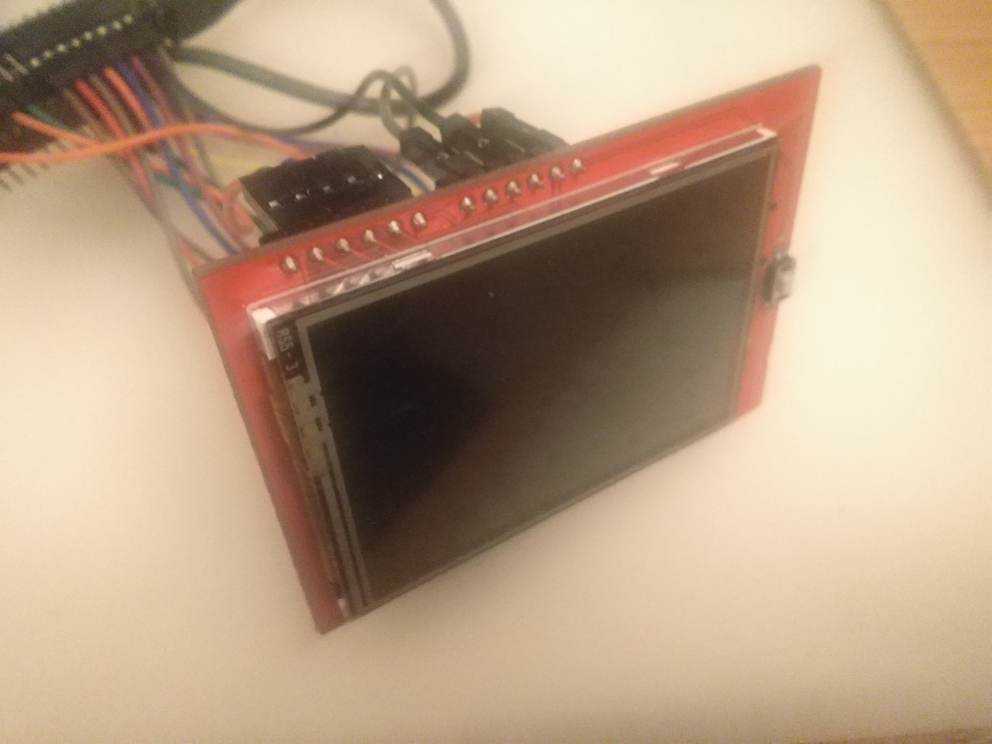
Hi community, I'm trying to read the touch screen values of 2.4" TFT display with no success. The display visual tests are running successfully. I have written a small script based on 'diagnose_touchpins" example, because I use Wemos Lolin32 board and the pins are different. Here is the code:
and that is the results, but many values are different at every execution of the code, where is the touch connected?:
Some images:
Please help.