 prusa3d-bb
commented
6 years ago
prusa3d-bb
commented
6 years ago Hello,
Thank you for this. We will get back to you soon.
Best regards, — Jennes de Schutter Technical Support
PRUSA Research +420 222 263 718 +421 220 570 305 188/7a Partyzánská, 17000, Prague shop.prusa3D.com
For simple troubleshooting, please use: http://help.prusa3d.com
Please rate our reply ...be generous :-)
--- original message --- On Mon, Jan 29, 2018 at 11:42 am, notifications@github.com RH-Dreambox wrote:
The filament should, according to me, have a completely straight path through the Exrtuder unit.
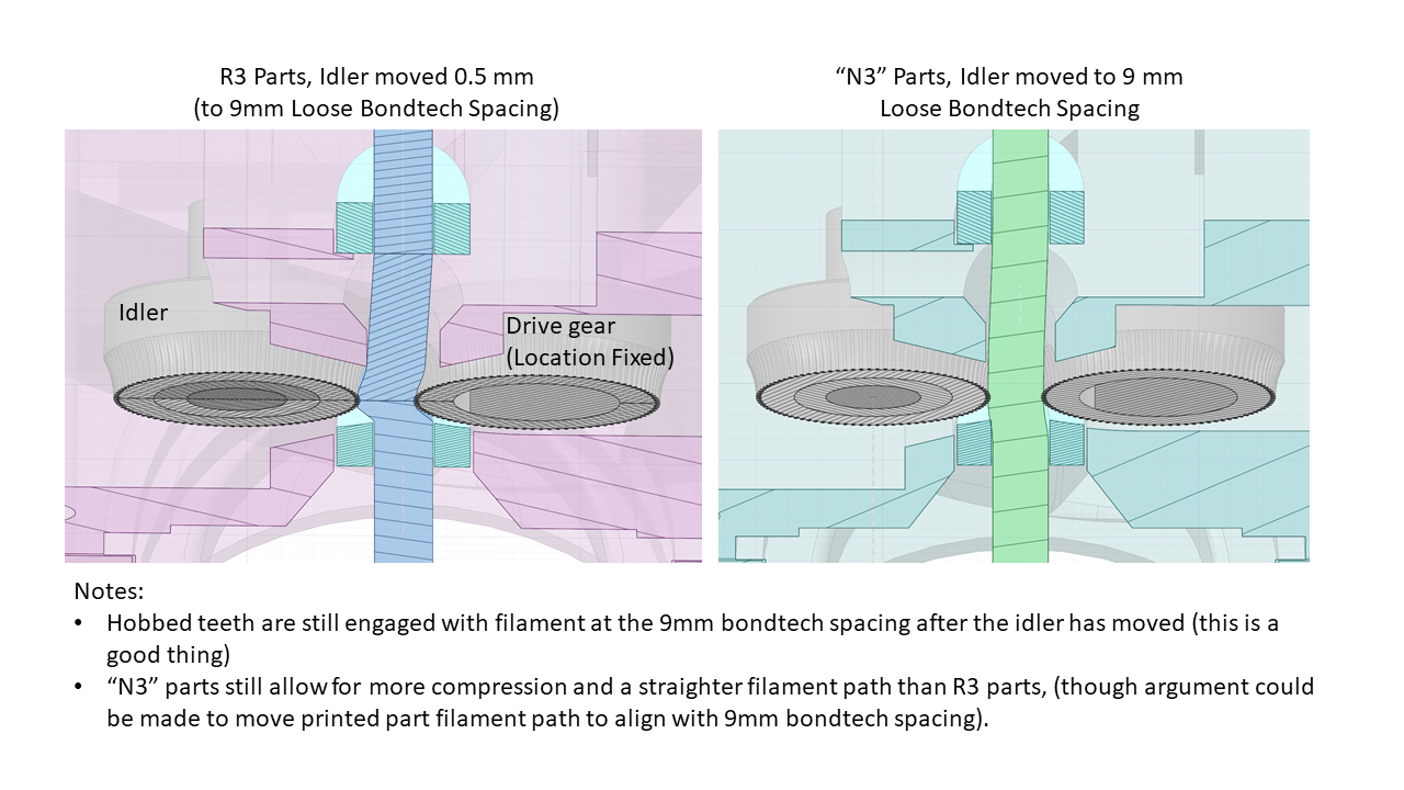
When I check the MK3 extruder, it seems that the extruder motor is seated 0.5 mm laterally.
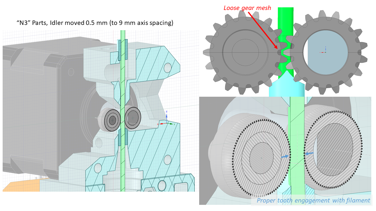
This means that the filament must be bent slightly to pass the engine's Bondtech pulley.
The center distance between the two Bontech wheels should be 9 mm and the center distance is determined by the two gear wheels (module 0.5).
The Bondtech gears can not be pushed together so it is a risk that you twist the extruder idler if is tightened too much.
The measurements are taken from Prusas download files.
https://shop.prusa3d.com/forum/original-prusa-i3-mk3-f30/fine-tune-your-e-axis-t13930.html
—
You are receiving this because you are subscribed to this thread.
Reply to this email directly, view it on GitHub, or mute the thread. --- end of original message ---
 ulfertg
 gregsaun
 chhu
chhu uscbutterworth
 ghost
ghost jltx1
jltx1 RH-Dreambox
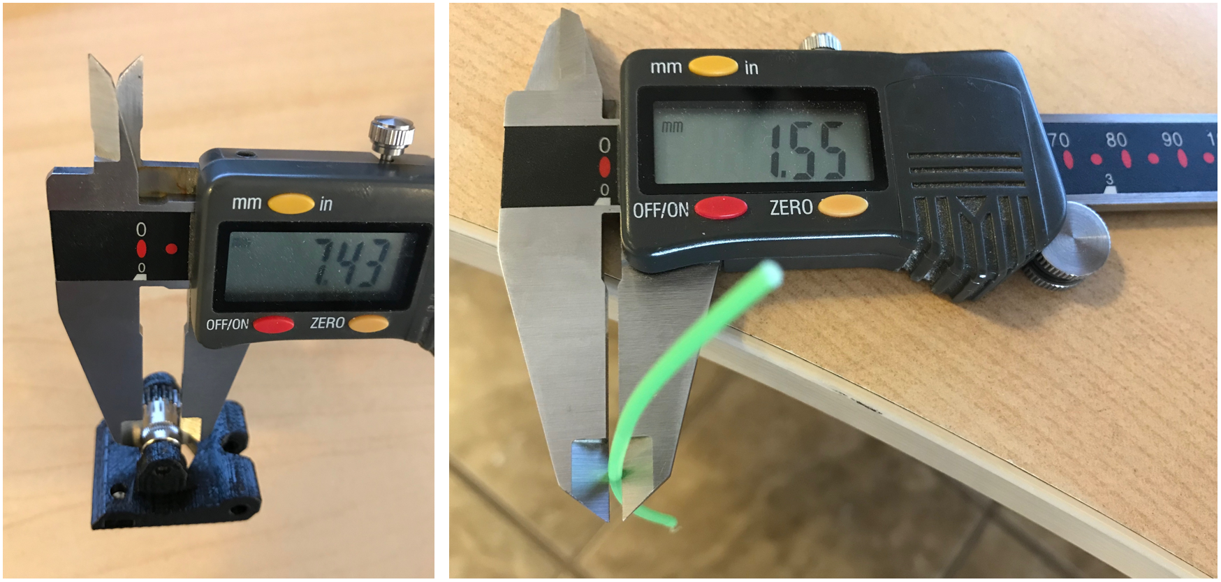
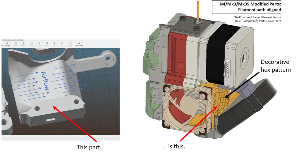
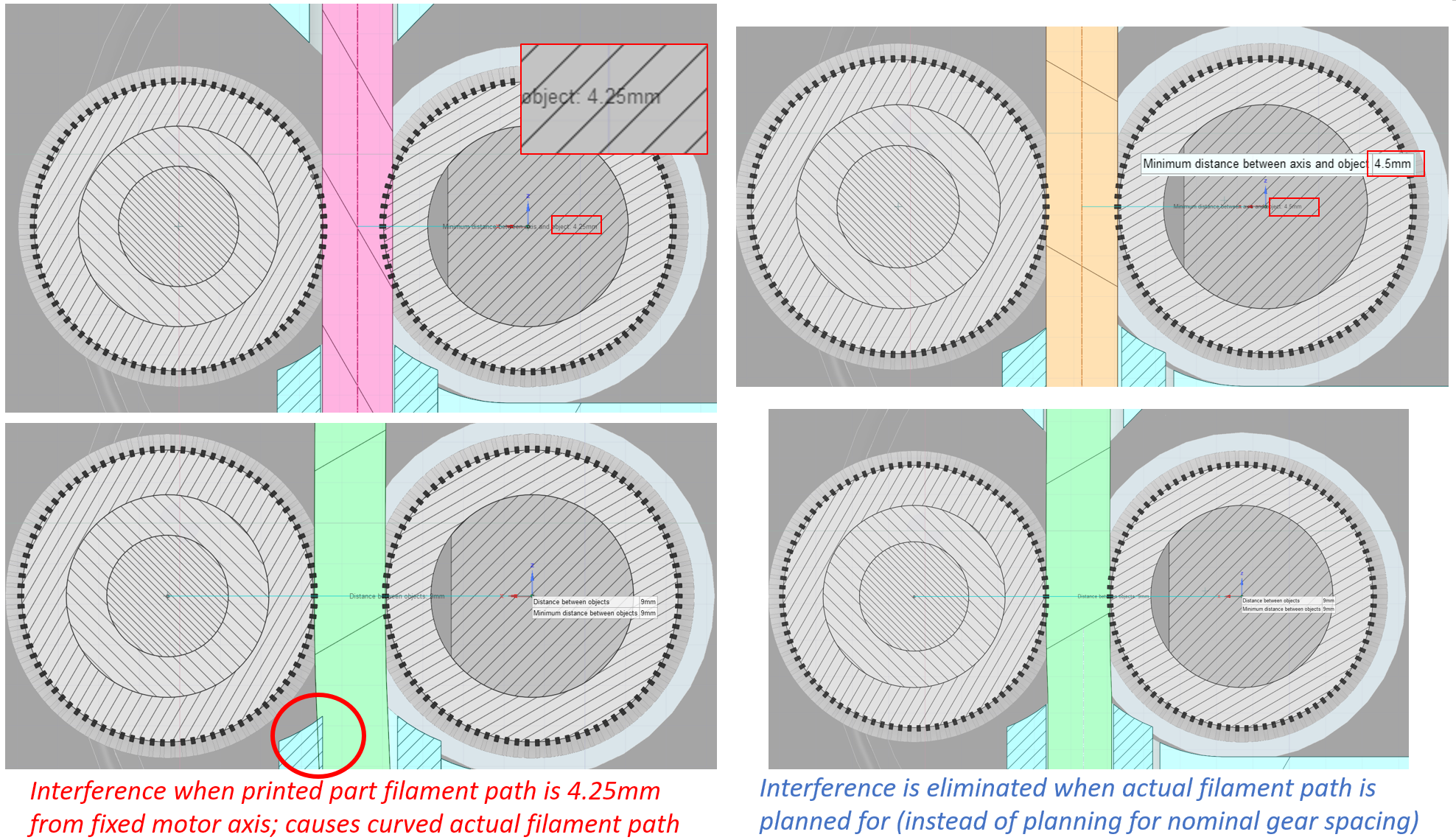 If the printed part filament path is placed at the midpoint between the two gears, it's going to be at 4.25 mm from the motor axis (see the image above, left side, pink indicates nominal printed part filament path). Once filament is loaded and the idler gear moves outward, the actual filament path also moves outward, and results in interference with the printed part filament path and the teflon tubes.
 Mike4U
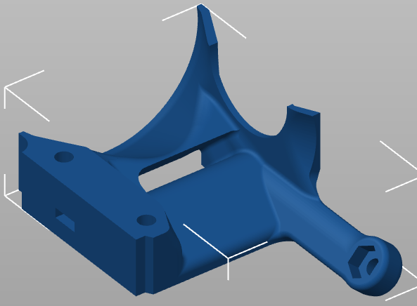
 This image shows the mmu2s version of the adapter-printer but the other appears similar. (Can't tell for sure because the step I have is messed up.)
 ManuGithubSteam

 mietek
 drandreas
 the-stu
 BNoiZe
The filament should, according to me, have a completely straight path through the Exrtuder unit. When I check the MK3 extruder, it seems that the extruder motor is seated 0.5 mm laterally.
This means that the filament must be bent slightly to pass the engine's Bondtech pulley. The center distance between the two Bontech wheels should be 9 mm and the center distance is determined by the two gear wheels (module 0.5).
The Bondtech gears can not be pushed together so it is a risk that you twist the extruder idler if is tightened too much. The measurements are taken from Prusas download files.
https://shop.prusa3d.com/forum/original-prusa-i3-mk3-f30/fine-tune-your-e-axis-t13930.html