 bubnikv
commented
4 years ago
bubnikv
commented
4 years ago This is due to the way PrusaSlicer (and the upstream slic3r) calculate the spiralized path. It is a simple hack, it just takes a horizontal slice, which it stretches along the Z axis. Therefore the two successive spiralized slices will show such a stepping artifact, if the two successive slices are not exactly the same.
There is a way to simulate the spiralized slice by interpolating the contour between the two successive slices, but it is a little bit involved to do right.
 suromark
 Kachidoki2807

 LuisHerrero92
 DavidBjerreBjoerklund
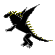 vorner
 Grummle
 kosteklvp
 clivius
 5jvm0u4

 animatorgeek
 degroof
 mjgoldberg
 SytanSD

 devoh747


 gmoissey
 yonitjio
 gaiuscosades
 rosenstand
 johnnydoesdesign
 QuiNz0r
 andrewboktor
 GuzziRaz
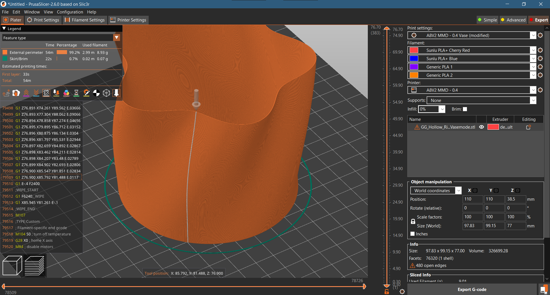
Version
2.1.0-beta2+
Operating system type + version
MacOS 10.13.6
3D printer brand / version + firmware version (if known)
TronXY X5S, Marlin 1.1.7-dev
Behavior
When generating gcode for vases, instead of a continuous path, there is a linear slanted seam across all layers visible in the preview that also appears in the printed object. It is independent of the shape, source or structure of the object, and shows up in the bottom right quadrant of the print area. Expected: seamless path along the perimeter Actual: slanted seam in print
Project File (.3MF) where problem occurs
Vase_Spiral_Matrjoshka.3mf.zip