Open mhugo opened 9 years ago
Good proposal here.
Having the abitlity to store default callout style in qgis profile would be nice so that we could provide default style for default install / custom confs.
Ok
A threshold to define the minimum distance between feature and label required to draw a line is necessary. I put a 2 mm screen tolerance in Easy Custom Labeling. Having it in display connector settings would be nice.
Indeed, that was also noticed by @nyalldawson
I had to put some magic on Vertical and horizontal label centering so that labels moved keep displayed correctly. See attached image. In short, If label is on the left, label alignement and anchor points data defined properties are set to the right of the label, and so on for every quadrant.
Good point.
@nyalldawson had a related comment:
I also think an exact relative x/y placement should be allowed for the start and end. MapInfo doesn't allow this and only gives positions eg "left of label", "right of label", etc, and it's no-way near flexible enough for precise cartographic placement of leading lines.
So ... I guess things should be thought out to be as flexible as possible: allowing automatic "intelligent" placement of the connector around the label or allowing precise x/y placement ?
Hi @mhugo
I really like this proposal - it has long been on my wish list. Could I suggest that the line style properties use the same style library and ui as normal vector line styles? I really like it when this has been done in e.g. composer properties - it creates a familiar and powerful capability to style lines just how you want them to look.
Regards
Tim
@timlinux Sure. That is planned. I will make it more explicit. Thanks
Updated text to better reflect remarks
In the current code base, the following methods would be modified: QgsPalLabeling::drawLabeling() : extract necessary property values and data-defined values for connectors
This needs to be updated to reflect the new labeling engine from 2.12
In order to be able to reuse the drawing code in other parts (possibly in a new symbology for lines), the classes needed to render the connectors will be part of the symbol layer class hierarchy (probably child of QgsLineSymbolLayerV2). It will consists mainly of new data properties to reflect properties listed above: lineStyle lineColor headStyle headColor tailStyle tailColor isCurved
I don't understand this... if it's reusing QgsLineSymbolV2, then line style, color will be determined by the line symbol layers from the symbol. The only changes required would be adding support to QgsLineSymbolV2 for drawing arrows and the start/end of lines. And I'd rather see that added as a seperate line symbol layer type, so it could be reused for styling line layers too.
Then, the new "connector" class would just need to store a QgsLineSymbolV2 to be used for rendering the connector.
(copying comments from previous PR)
I like the general direction this is going, with the exceptions noted above.
Have you thought about automatic creation of a connector when "display a connector" is enabled and the user first moves a label from it's automatic placement?
Also, what considerations have been given about automatic creation of dynamic connectors if a label is further than a specified tolerance from a feature? Hopefully we'll eventually also see support for that in QGIS, so this work should be done allowing for that possibility in future.
@nyalldawson For the symbology classes: true. Actually, storing a QgsLineSymbolV2 should be enough and MarkerLineSymbolLayers as head and tail symbol layers. The automatic creation of connectors was already mentioned, I've updated the text to make it more explicit
Thanks
This feature would be amazing.
It would be useful if the connectors could take advantage of existing conflict detection engines such that
For example, let the user specify a "set" of connector types that the placement engine can use in it's efforts to minimize distance of labels from features and prevent connectors from crossing. The "set" of connectors can for example be lines, all of the same style, but with either 1 2 or 3 elbows.
@BioScientist Hi, until now, I think we have been talking about manual labeling and callouts. Your point raises the very interesting feature of automatic callout. I think that implies labeling engine can test position for labels using variable distance to features. Currently, it can test positions at fixed distance. @mhugo @nyalldawson @timlinux @NathanW2 : Any idea if PAL is able to go this way?
Interesting.
As a first step, I would see some additional helper tools that would allow to "uncross" connector lines for a given set of selected labels, for instance by choosing the correct order along a vertical or horizontal line. That would not be part of the placement engine, but would assist the user in placing connectors. We would also add tools found in tools like Inkscape to align a set of labels horizontally or vertically.
Adding lots of candidate positions around the feature to the placement engine could be interesting to investigate as well in a future version.
Another point raised here: https://github.com/haubourg/EasyCustomLabeling/issues/8#issuecomment-159564864 Rotating map canvas should keep connector recomputed "flat on screen" when the callout is of the type with a flat/ vertical part and a connection part to the object. If we have a straight or curved connector. Label alignement shoudl also reflect that. Régis
Added a comment about canvas rotation
@NathanW2 Can we tag it as "final draft" ?
@nyalldawson @dakcarto comments? You guys know the label stuff the best.
@mhugo is the actual text of the QEP here up to date? I'm wondering about the mockup of the "display a connector" ui, as I thought this would instead reuse the existing line symbology UI.
I'm also unsure about the wording of
In particular, lines of the connector will be drawn thanks to a QgsLineSymbolV2 with properly defined symbol layers (QgsMarkerLineSymbolLayerV2 for instance for head and tails)
I think this should probably be made simpler than adding marker line symbols for the start/end and correctly defining the angle of these. I'd personally rather see this added as a new symbol layer itself to take the bulk of the effort away from users who want to create these.
It would be useful if the connectors could take advantage of existing conflict detection engines such that the connector lines don't cross (or are discouraged from crossing),
This should be possible now - the labeling engine supports registering separate "obstacle" features, which act as obstacles to other labels/diagrams but don't draw any themselves.
@nyalldawson The idea behind using markers for the arrow start/end was to offer all the possibilities we have with marker layers (simple markers, SVG, etc). But I agree we cannot let the user rotate them manually. So i'm ok with your proposition of having a symbol layer that deals with markers unless I find a way to reuse markers and forcing their rotation (?)
About the UI, I've updated the mockups. There will be a new labeling property to display a connector and then the user can choose a line symbol, and especially a new "connector/arrow" line symbol layer. Is it better ?
It would be useful if the connectors could take advantage of existing conflict detection engines such that the connector lines don't cross (or are discouraged from crossing),
This should be possible now - the labeling engine supports registering separate "obstacle" features, which act as obstacles to other labels/diagrams but don't draw any themselves.
You're right, but It think it was referring to the fact that we may want to avoid line connectors to cross. As it's done in graph visualisation libraries for instance to organize edges so that they do not overlap too much.
@nyalldawson @mhugo Hi guys, I may have not understood things well, but currently user do not have to rotate marker angle manually to draw an arrow. A simple line + a symbol maker line on end point with rotation option enabled does the trick
Saving a few default "arrow" styles in symbol library could be enough.
@haubourg indeed ... thanks for your remark. So @nyalldawson what do you find complex in having symbol layers for start/end points ?
I would like to move on these QEP. Some remaining questions / objections ? Could it be voted ?
Nyall?
On Thu, Apr 21, 2016 at 11:00 PM, Hugo Mercier notifications@github.com wrote:
I would like to move on these QEP. Some remaining questions / objections ? Could it be voted ?
— You are receiving this because you were mentioned. Reply to this email directly or view it on GitHub https://github.com/qgis/QGIS-Enhancement-Proposals/issues/47#issuecomment-212906733
Sorry - yes, it's a +1 from me.
One last thing I thought of last week - I'd love it if the code for calculating the shape of the connector could be implemented in its own separate class so that we can potential reuse this outside of labelling.
Agreed with @nyalldawson. @mhugo isn't there a work in progress for cuirved connectors in layer's symbology. Could that be common code?
@nyalldawson @haubourg sure, that should not be a problem. Thanks
Text updated to better explain how a connector is defined
It's a +1 from @nyalldawson . @timlinux can we interpret your message as a +1 ?
+1 from me too!
May I ask which is exactly the current state of this enhancement?
@rogorido I think it became a plugin: https://github.com/haubourg/EasyCustomLabeling available as:
thanks, but are there any plans to adapt it to qgis3? I have the impression it does not work very well with the last versions and the last change was many months ago... Is it still in active development?
@haubourg still updating this?
@rogorido I see that last version is indeed April 30 2017. Fact is that plugin authors are doing this in their own time, so need either time or some encouragement maybe :-)
@rduivenvoorde thanks. As far as I see, there are no plans to integrate this functionality into the core of qgis?
@rduivenvoorde in fact, EasyCustomLabeling was the proof of concept in QGIS2 and helped me survive to the user's demands :) Then, in my previous lif, I funded the QEP made by @mhugo . Then my previous employer joined to the French Ministry of ecology funded the auxiliary storage, editable joins, which were the prerequisites - and the hardest parts. Then.... I left... and the next development about labeling connectors, connector paths remained unfunded, which makes me a bit sad given the importance of such a basic feature in a GIS. So it's still opened, we would be really happy to have it funded and become a reality. Feel free to contact us if you are in situation to fund that.
@haubourg still updating this?
and no, I just upgraded it to QGIS 3 at Essen hackfest, but I wrote for in my previous employer, and the plan was to get rid of that bad piece of beginner code to a proper port to the core.
For reference, QGIS 3.10 added support for native label callouts, and QGIS 3.20 will see interactive movement of these callouts: https://github.com/qgis/QGIS/pull/41724
Yeah!
QGIS Enhancement 47: Label connectors
Date October 2015 Author Hugo Mercier Contact hugo dot mercier at oslandia dot com Last Edited Status
Version QGIS 2.14
Summary
This proposal is aiming at adding to the labeling display engine the possibility for the user to define "connectors" between labels and the features they label.
Current state
The current version of QGIS allows to manually place labels when the output of the automatic placement mechanism is not enough.
It relies on "data defined" properties. Indeed, the X and Y positions of a label as well as its rotation angle can be defined by a data column or any expression.
Some graphical controls allow then to manually manipulate these properties. The state of a label can be changed from being automatically placed to being manually placed (pinning/unpinning). When they are pinned, labels can then be moved or rotated by interaction of the user. Positions and rotations data are then updated in columns of the layer.
Proposed improvements
It may be desirable to have visual "connectors" between the label and the feature it refers to. They are a generalization of "arrows", as it can be found in drawing programs: single arrows, straight lines or curves. Connectors are "attached" to a label: if one of the two endings (either the label or the feature) is moved, the shape of the connector is recomputed and a display refresh is needed.
This QEP is not meant to give an exhaustive list of possible connectors. The idea is to have a generic implementation with the most common types of connectors and everything needed in the code to be able to add new types in the future.
Possible types of connectors:
A connector will be defined in two steps :
Placement of the two ends will then need additional properties:
Illustration of the "intelligent" quadrant positioning. The positioning on the side of the label depends on the position on the side of the feature. It is chosen in order to minimize the length / complexity of the connector.
Some connectors may be defined by the help of additional control points : for straight lines with angles between them or for Bézier curves.
Each connector is then defined by a line made by a certain amount of points. They may be rendered by line symbol layers, such as « simple line » or « arrows ».
New line symbol layers will also be added to render the body of the connector (note that this could also be implemented as options to pre-existing symbol layers) :
Arrow heads could be rendered by using marker symbol layers with correct options (new predefined « arrows » symbols will be added)
The user may also choose to render the connector with a « filled arrow » symbol layer, as it is done in the « arrows » symbol layer. The « arrows » symbol layer may be extended to support quadratic and cubic Bézier arrows.
Connector must be drawn with respect to the current map canvas rotation. If parts of the connector is supposed to be drawn "straight" (horizontally or vertically), they must be updated when the canvas is rotated
Implementation details
Connectors are drawn to the Qt canvas, using the QPainter API. The existing symbology code will be reused when possible. In particular, lines of the connector will be drawn thanks to a QgsLineSymbolV2 with properly defined symbol layers (QgsMarkerLineSymbolLayerV2 for instance for head and tails)
The following classes / methods would be modified:
GUI Changes
New labeling properties will be available. They will be splitted into different parts : properties of the two connector ends, number and types of the control points and style.
(UI sketchup, not the final one)
Then the style could be defined by a set of symbol layers :
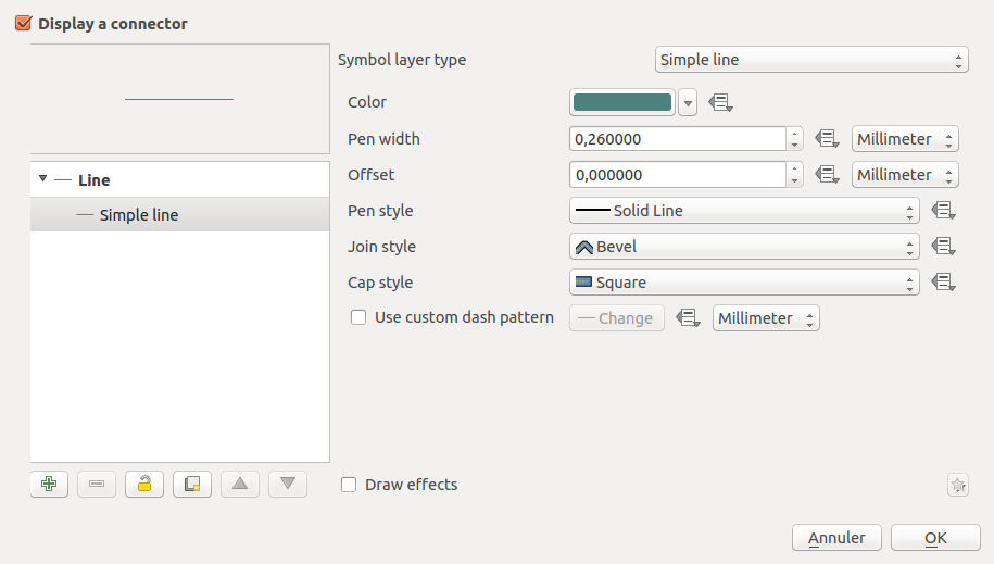
Each of the property could also be data-defined (not represented here).
From the user perspective, new tools will be available to easily manipulate label connectors. To be consistent with current label manual placement toolboxes, new controls will be added to manually place control points for connector types that need them.
Optionally, it would be nice for the user to be able to edit per-connector properties, i.e. properties that are data-defined via a GUI dialog. This could be achieved by reusing the connector properties dialog and connecting it to one particular feature.
Automatic creation of connectors
A new labeling option will allow to automatically create a label connector if the label is manually placed at some distance from its feature. Automatic creation of fields for the handling of connector properties would be provided through the use of auxiliary fields (see corresponding QEP), meaning it would be transparent for the user to move a label from its automatic placement and see a connector appear (with default options)