 jordens
commented
4 years ago
jordens
commented
4 years ago Feature preview: five tones around 125 MHz, different amplitudes. Still several things to implement.

Closed jordens closed 4 years ago
jordens
commented
4 years ago Feature preview: five tones around 125 MHz, different amplitudes. Still several things to implement.
jordens
commented
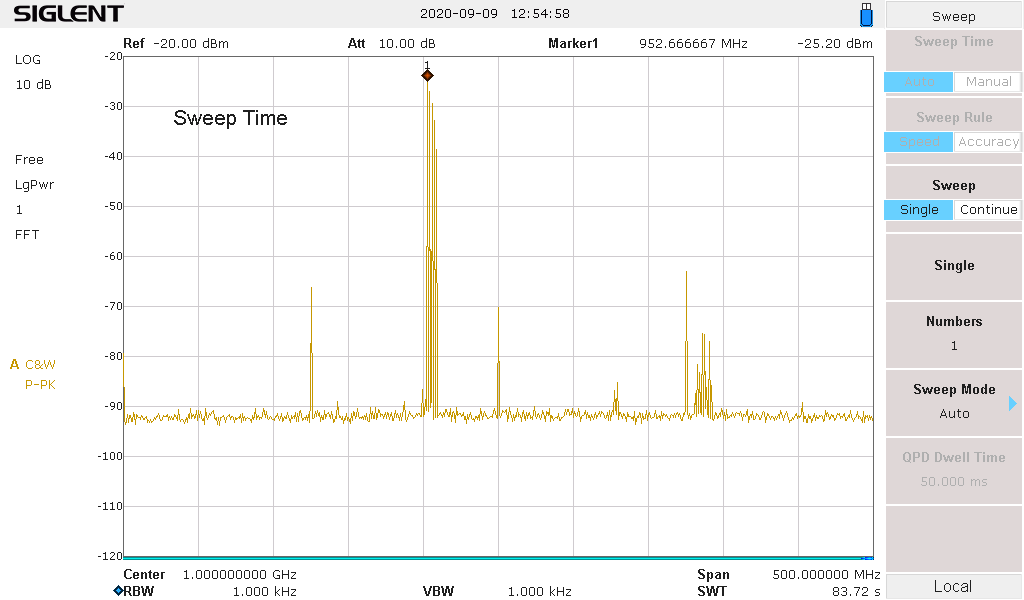
4 years ago And with the upconverters (5 tones at -1.67 MHz multiples on coredevice, duc to -164 MHz on phaser, 2x interpolation and cmix -125 MHz on dac, upconverter carrier at 1.25 GHz), showing good IMD, phase spur, carrier suppression, IQ balance.

 hartytp
commented
4 years ago
hartytp
commented
4 years ago Nice!
@jordens out of curiosity, there looks to be quite a bit of close in noise. Any idea where that's from? On the baseband plot, the multi-tone SFDR looked to be about 40dB. Is that what you'd expect?
jordens
commented
4 years ago There is no interpolation (only zero order hold from 25 MS/s to 500 MS/s) yet so there are copious amounts of aliases flying around. The first shot is also with the Phaser DUC at zero frequency so they have a good chance of appearing close in. In the second shot they are (conveniently) outside the 40 MHz bandwidth of the scan. The pedestal noise in the first shot is either a bug that I fixed on the way or an analyzer limitation (settings were different). In the second shot it's likely analyzer. Neither test is meant to measure or characterize anything. I wouldn't worry.
hartytp
commented
4 years ago cool, that's what I wanted to hear
jordens
commented
4 years ago With the complete interpolation chain, settings as before. The obviously required PLL tuning, LF debugging, IQ balancing, carrier nulling, delay matching, and phase noise measurement will need to be done by someone else. I don't see anything that looks like it's introduced in the digital domain. Note that there is no common reference, no locking and the devices are strewn across a table in the breeze.


The analyzer's own 10 MHz reference for comparison.

hartytp
commented
4 years ago cool! What are peaks 2/3 in the top plot?
hartytp
commented
4 years ago LF debugging, IQ balancing, carrier nulling, delay matching, and phase noise measurement will need to be done by someone else
What do you mean by "LF debuggin" and "delay matching"?
jordens
commented
4 years ago jordens
commented
4 years ago Also note that the complete design uses about 10% of the resources (DSP, LUT/FF) of the xc7a100t on Phaser. A 15t would still have plenty of space and there is room for resource optimization.
hartytp
commented
4 years ago Analog I-Q delay matching from the DAC to the upconverter. The digital delays are matched already.
That's nominally done in the design, right? You just mean that it may need tuning in practice to get good sideband suppression at multiple frequencies due to component tolerances etc.
hartytp
commented
4 years ago 2/3 looks like a upconverter PLL instability (as I said, no attempt at verifying the parameters, these were those from Greg's screenshot elsewhere).
ack. Looking at the phase noise/loop filters is on my testing list once the gateware/driver is finished.
Am I right in thinking that modulo issues like sub-optimal PLL tuning, this is now basically ready for use in experiments? Or are the register abstractions required to do much with it?
jordens
commented
4 years ago Analog I-Q delay matching from the DAC to the upconverter. The digital delays are matched already. That's nominally done in the design, right?
There are multiple knobs for I-Q group delays, qmc scalings and offsets and phases, upconverter offsets. They are all nominally good but there may well be a couple dozen dB of improvement in there. Group delays might be a bit more interesting to optimize properly but might also not bring that much gain for typical experiments.
Am I right in thinking that modulo issues like sub-optimal PLL tuning, this is now basically ready for use in experiments? Or are the register abstractions required to do much with it?
The coredevice layer needs some SI-to-mu conversion methods. And there may be a bit of register abstraction coming but I'm not sure it'll go very far since there can't really be a meaningful abstraction beyond those registers. There will be some default settings and going beyond them will require reading the datasheets. The only user-facing adjustables required now are means to set the upconversion frequencies (on Phaser, FMIX/CMIX in the DAC and the TRF VCO).
This is definitely ready to be characterized in depth and used in early experiments to get some more experience with it and find the most prominent bugs.
hartytp
commented
4 years ago This is definitely ready to be characterized in depth and used in early experiments to get some more experience with it and find the most prominent bugs.
Perfect!
There are multiple knobs for I-Q group delays, qmc scalings and offsets and phases, upconverter offsets. They are all nominally good but there may well be a couple dozen dB of improvement in there. Group delays might be a bit more interesting to optimize properly but might also not bring that much gain for typical experiments.
ack
The coredevice layer needs some SI-to-mu conversion methods. And there may be a bit of register abstraction coming but I'm not sure it'll go very far since there can't really be a meaningful abstraction beyond those registers. There will be some default settings and going beyond them will require reading the datasheets. The only user-facing adjustables required now are means to set the upconversion frequencies (on Phaser, FMIX/CMIX in the DAC and the TRF VCO).
ack, so long as there is some way of playing with CP gain etc I'm happy (it's fine if this needs some familiarity with the data sheet, as ultimately it will be a matter of doing some playing to pick sensible defaults which most users will likely not touch).
jordens
commented
4 years ago Without further investigation, I suspect that there need to be some changes to the baseband version analog AA filter and/or load as there is lots of IMD with the nominal DAC current of 20 mA FS. If I dial it down to 9 mA, the output looks good and SFDR is still limited by IMD and no concerning clearly digital spurs in sight.


Some more datasheets and manuals about that filter/termination:
hartytp
commented
4 years ago @jordens in the support list above, I didn't see phase synchronisation. What's the plan/timeframe for that?
jordens
commented
4 years ago Deterministic latency is already built in. I just haven't verified it.
hartytp
commented
4 years ago great, thanks for clarifying.
jordens
commented
4 years ago Remaining topics broken out. Closing.
This is a running list of the implementation milestones
Phaser baseline
example.pyintophaser.init())kasli_tester#8