 lurch
commented
3 years ago
lurch
commented
3 years ago Open jakecrowley opened 3 years ago
lurch
commented
3 years ago  jakecrowley
commented
3 years ago
jakecrowley
commented
3 years ago See https://github.com/raspberrypi/pico-sdk/issues/88#issuecomment-774113818 ?
Yeah, I have looked at that. The problem is that solution only works for master mode, and I need this functionality for slave mode. As far as I can tell the only fix would be to reimplement SPI as a PIO state machine, however I'm pretty new to this stuff so I could be wrong.
lurch
commented
3 years ago I'm not very familiar with SPI code (and so there may be a better workaround than what I'm suggesting), but would changing your spi_read_blocking call to only read a single byte at a time be a viable workaround?
...or maybe using just a single SPI.transfer(buf, 14) on the Arduino side would also work? https://www.arduino.cc/en/Reference/SPITransfer :shrug:
jakecrowley
commented
3 years ago I'm not very familiar with SPI code (and so there may be a better workaround than what I'm suggesting), but would changing your
spi_read_blockingcall to only read a single byte at a time be a viable workaround? ...or maybe using just a singleSPI.transfer(buf, 14)on the Arduino side would also work? https://www.arduino.cc/en/Reference/SPITransfer 🤷
I have tried something similar to what you are suggesting. I looked into how the spi.c file and saw that the spi_read_blocking function uses spi_get_hw(spi)->dr to pull the byte from the SPI bus directly, so I just ran that through a while loop but unfortunately got the same result. Looking at the clock line through my logic analyzer each pulse is only around 250 nanoseconds which is probably way too fast to try something like that.
Like I said, I am new to the pico and state machine stuff but maybe there would be a way to just reimplement the protocol and pull the bits from the data line on the rising edge of the clock signal while the SS pin is low?
Also, changing the way the code on the Arduino side works wouldn't help since I was only using that for troubleshooting, I would like to be able to interface with existing hardware in the end.
jakecrowley
commented
3 years ago It actually seems like something similar to what I was thinking of is actually already implemented in the clocked_input.pio example. I'll give it a try and see if this works as a solution to my issue.
jakecrowley
commented
3 years ago Good news, the clocked input pio example actually works as-is, as it completely ignores the CS line all together. However, I would like to request an actual SPI implementation rather than just reading in data on a clock signal.
lurch
commented
3 years ago  Wren6991
commented
3 years ago
Wren6991
commented
3 years ago This code sends the byte array buffer over SPI, setting CS to LOW, completing the transfer, then setting CS back to HIGH, as this is how the SPI protocol is supposed to function. However, in doing so, the Pico only receives the first byte of each transfer, waiting until it recieves 14 bytes and then displaying all the first byte.
This is how one variant of SPI functions. Unfortunately the PL022 doesn't support this variant in slave mode.
To do this with PIO, you could try something like the following (just a sketch, not promising there are no typos):
.program clocked_input_chip_select

; Sample bits using an external clock, and push groups of bits into the RX FIFO.
; - IN pin 0 is the data pin
; - IN pin 1 is the clock pin
; - JMP pin is the chip select
; - Autopush is enabled, threshold 8
;
; This program waits for chip select to be asserted (low) before it begins
; clocking in data. Whilst chip select is low, data is clocked continuously. If
; chip select is deasserted part way through a data byte, the partial data is
; discarded. This makes use of the fact a mov to isr clears the input shift
; counter.

flush:
    mov isr, null         ; Clear ISR and input shift counter
    jmp check_chip_select ; Poll chip select again

.wrap_target
do_bit:
    wait 0 pin 1          ; Detect rising edge and sample input data
    wait 1 pin 1          ; (autopush takes care of moving each complete
    in pins, 1            ; data byte to the FIFO)
check_chip_select:
    jmp pin, flush        ; Bail out if we see chip select high
.wrap
This uses the PINCTRL_JMP_PIN config to select the GPIO used for chip select, so this can be any GPIO, independent of the other pin mappings.
 MikeLoh
commented
2 years ago
MikeLoh
commented
2 years ago Hello, I know issue was indicated closed - but I was curious and did a deeper dive into the reason for SPI issue receiving only first byte in slave mode. The reason can be found on page 535 of current RP2040 Datasheet.
However, in the case of continuous back-to-back transmissions, the SSPFSSOUT signal must be pulsed HIGH between each data word transfer. This is because the slave select pin freezes the data in its serial peripheral register and does not permit it to be altered if the SPH bit is logic zero. Therefore, the master device must raise the SSPFSSIN pin of the slave device between each data transfer to enable the serial peripheral data write. On completion of the continuous transfer, the SSPFSSOUT pin is returned to its idle state one SSPCLKOUT period after the last bit has been captured.
Solution for now would be to use interrupt on chip select (which was suggested before) to enable and disable internal SPI accordingly. The RP2040 datasheet details how this is done - not positive of support in Pico SDK. Plan to look further in coming week.
Wonder though, is there a PIO state machine that can do same with internal SPI hardware making the chip select operate more like we are all expecting where chip select is held? I still have lots to learn about PIO.
 suicidaleggroll
commented
2 years ago
suicidaleggroll
commented
2 years ago Another comment for this closed thread, MikeLoh is absolutely right that this is mentioned in the datasheet, but one quick note on that, the RP2040 behavior is different depending on the SPI phase. His quote above is for SPH=0, while below is the datasheet comment for SPH=1.
In the case of a single word transfer, after all bits have been transferred, the SSPFSSOUT line is returned to its idle HIGH state one SSPCLKOUT period after the last bit has been captured. For continuous back-to-back transfers, the SSPFSSOUT pin is held LOW between successive data words and termination is the same as that of the single word transfer.
I've tested this myself, and indeed if you operate the SPI with CPHA=1 (CPOL doesn't matter for this), the SPI slave will operate correctly in the "standard" way and will receive all bytes with CS staying low for the duration of the transfer. It's very odd to me that changing the SPI phase would have this effect, but it might be a usable workaround for some people.
MikeLoh
commented
2 years ago @suicidaleggroll I had discovered this same workaround and also have successfully tested. Fortunately it will work with our implementation to have SPH=0, giving us the operation we expect.
Sorry, had not gotten around to posting this update to here.
I currently have an Arduino Mega in SPI master mode, and a RPi Pico in slave mode, communicating over SPI. I was using the mega to troubleshoot some issues I was having.
My pinout is:
Here is the Pico's code:
and here is the Arduino's code:
This code sends the byte array buffer over SPI, setting CS to LOW, completing the transfer, then setting CS back to HIGH, as this is how the SPI protocol is supposed to function. However, in doing so, the Pico only receives the first byte of each transfer, waiting until it recieves 14 bytes and then displaying all the first byte.
Pico serial output: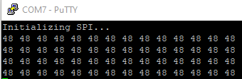
After doing some fiddling around with the code, I realized that if I change the loop to toggle CS on each byte sent, the Pico successfully receives all of the data.
New Pico serial output: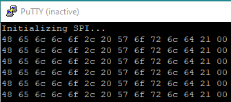
However, this is not how the SPI protocol should operate and makes the Pico incompatible with pretty much every SPI master device, and seems to be an issue in the pico's hardware_spi library, unless this is user error and if that is the case then I will gladly be corrected.