 BorretSquared
commented
1 year ago
BorretSquared
commented
1 year ago Would kill for this.
Open PicoPlanetDev opened 1 year ago
BorretSquared
commented
1 year ago Would kill for this.
 PicoPlanetDev
commented
1 year ago
PicoPlanetDev
commented
1 year ago I submitted a pull request but no news on it for a few months. In the meantime, I've got my fork https://github.com/PicoPlanetDev/OPi.GPIO that simply copies the Zero2 mapping to a new Zero3 file. This has been working flawlessly on my own Zero3 so far. Maybe this helps, although let me know if you want me to flesh it out a little further if needed.
 techsd
commented
1 year ago
techsd
commented
1 year ago OrangePi Zero2 has 26 GPIO pins, and OrangePi Zero3 has 28. OrangePi Zero2 has 4 UART pins, and OrangePi Zero3 has 2. OrangePi Zero2 has 2 SPI pins, and OrangePi Zero3 has 1. OrangePi Zero2 has 1 I2C pin, and OrangePi Zero3 has 2.
Pin | OrangePi Zero2 | OrangePi Zero3 -- | -- | -- GPIO0 | UART0 TX | UART0 TX GPIO1 | UART0 RX | UART0 RX GPIO2 | UART1 TX | GPIO2 GPIO3 | UART1 RX | GPIO3 GPIO4 | SPI0 MOSI | SPI0 MOSI GPIO5 | SPI0 MISO | SPI0 MISO GPIO6 | SPI0 SCLK | SPI0 SCLK GPIO7 | SPI0 CE0 | GPIO4 GPIO8 | SPI0 CE1 | GPIO5 GPIO9 | I2C0 SCL | I2C0 SCL GPIO10 | I2C0 SDA | I2C0 SDA GPIO11 | GPIO11 | GPIO11 GPIO12 | GPIO12 | GPIO12 GPIO13 | GPIO13 | GPIO13 GPIO14 | GPIO14 | GPIO14 GPIO15 | GPIO15 | GPIO15 GPIO16 | GPIO16 | GPIO16 GPIO17 | GPIO17 | GPIO17 GPIO18 | GPIO18 | GPIO18 GPIO19 | GPIO19 | GPIO19 GPIO20 | GPIO20 | GPIO20 GPIO21 | GPIO21 | GPIO21 GPIO22 | GPIO22 | GPIO22 GPIO23 | GPIO23 | GPIO23 GPIO24 | GPIO24 | GPIO24 GPIO25 | GPIO25 | GPIO25 GPIO26 | GPIO26 | GPIO26 GPIO27 | GPIO27 | GPIO27 GPIO28 | GPIO28 | GPIO28pin number = (position of letter in alphabet - 1) 32 + pin number So, PD14 will be (4 - 1) 32 + 14 = 110
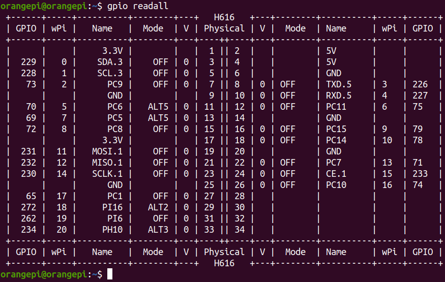
`# Orange Pi Zero 3 physical board pin to GPIO pin BOARD = { 3: 229, # PH5/I2C3_SDA 5: 228, # PH4/I2C3_SCK 7: 73, # PC9 8: 226, # PH2/UART5_TX 10: 227, # PH3/UART5_RX 11: 70, # PC6 12: 75, # PC11 13: 69, # PC5 15: 72, # PC8 16: 79, # PC15 18: 78, # PC14 19: 231, # PH7,SPI1_MOSI 21: 232, # PH8,SPI1_MISO 22: 71, # PC7 23: 230, # PH6,SPI1_CLK 24: 233, # PH9,SPI1_CS 26: 74, # PC10 27: 234, # PH10/UART6_TX 28: 235, # PH11/UART6_RX 29: 236, # PH12/I2C4_SDA 30: 237, # PH13/I2C4_SCK 31: 238, # PH14/SPI2_MOSI 33: 239, # PH15/SPI2_MISO 34: 240, # PH16/SPI2_CLK 35: 241, # PH17/SPI2_CS 36: 242, # PH18/UART7_TX 37: 243, # PH19/UART7_RX }
BCM = BOARD `
 JMVS
commented
5 months ago
JMVS
commented
5 months ago Is this helpful at all?
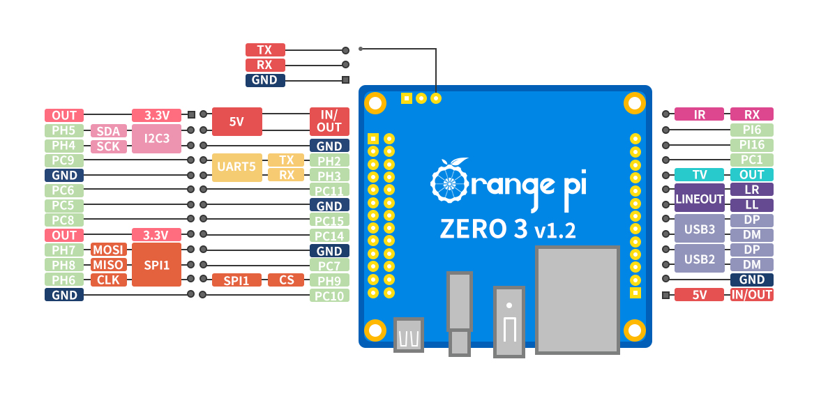
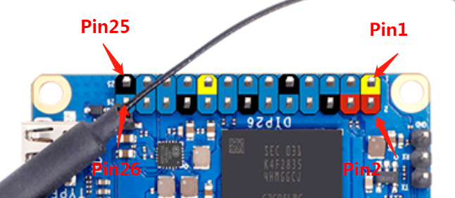
Taken from: http://www.orangepi.org/orangepiwiki/index.php/Orange_Pi_Zero_3#26_Pin_Interface_Pin_Description
The Orange Pi Zero 3 uses an Allwinner H618 processor which appears to be very similar to the H616 used in the Zero 2. In fact, the pin mappings may even be identical. Here's a link to the Zero 3 schematic: OrangePi-Schematic of ZERO3.pdf
As soon as I get my Zero 3 in the mail, I'll see if I can figure out the physical to GPIO pin mappings and create a pull request. In the meantime, I'd love to hear if anyone has experimented with it yet!