robbievanleeuwen / section-properties

Analysis of an arbitrary cross-section in python using the finite element method.
https://sectionproperties.rtfd.io
MIT License
422 stars 92 forks source link

General comments #1

Closed Agent6-6-6 closed 5 years ago

Agent6-6-6 commented 5 years ago

Describe the bug For a section made up of multiple CustomSections only the last mesh size defined seems to be being applied to all custom sections (with the others not being taken into account). Not sure if I am interpreting how it should be working incorrectly or not.

To Reproduce Steps to reproduce the behavior: Run the following, play with mesh sizes and see that first 4 have no effect on the mesh being generated.

import sectionproperties.pre.sections as sections
from sectionproperties.analysis.cross_section import CrossSection

def built_up_I_section():
    d = 380
    b = 100
    t_f = 17.5
    t_w = 10
    r = 0
    n_r = 1
    I_section = sections.ISection(d=d, b=b, t_f=t_f, t_w=t_w, r=r, n_r=n_r, shift=[-b / 2, -d / 2])
    weld_leg_size = 20
    # create 'welds'
    points1 = [[0, 0], [weld_leg_size, 0], [0, weld_leg_size]]
    points2 = [[0, 0], [-weld_leg_size, 0], [0, weld_leg_size]]
    points3 = [[0, 0], [weld_leg_size, 0], [0, -weld_leg_size]]
    points4 = [[0, 0], [-weld_leg_size, 0], [0, -weld_leg_size]]
    facets = [[0, 1], [1, 2], [2, 0]]
    holes = []
    control_points1 = [[0, 0]]
    control_points2 = [[0, 0]]
    control_points3 = [[0, 0]]
    control_points4 = [[0, 0]]
    weld1 = sections.CustomSection(points1, facets, holes, control_points1, shift=[t_w / 2, -d / 2 + t_f])
    weld2 = sections.CustomSection(points2, facets, holes, control_points2, shift=[-t_w / 2, -d / 2 + t_f])
    weld3 = sections.CustomSection(points3, facets, holes, control_points3, shift=[t_w / 2, d / 2 - t_f])
    weld4 = sections.CustomSection(points4, facets, holes, control_points4, shift=[-t_w / 2, d / 2 - t_f])

    # create a list of the customsections to be merged
    section_list = [I_section, weld1, weld2, weld3, weld4]

    # merge the 5vsections into one geometry object
    geometry = sections.MergedSection(section_list)

    # clean the geometry
    geometry.clean_geometry()
    geometry.plot_geometry()  # plot the geometry

    # create a mesh - in this line the last 10 mesh size is applied to all of the customsections, first 4 values are ignored
    mesh = geometry.create_mesh(mesh_sizes=[100, 100, 100, 100, 10])

    # create a CrossSection object
    section = CrossSection(geometry, mesh)
    # section.display_mesh_info()  # display the mesh information
    section.plot_mesh()  # plot the generated mesh

Expected behavior Based on the above code and based on examples in the readme/readthedocs for built up sections I would have expected that the I section and first three triangular areas representing welds would have a different mesh size to the last triangular area.

Screenshots Results showing similar 10 mesh for all customsection elements Figure_1

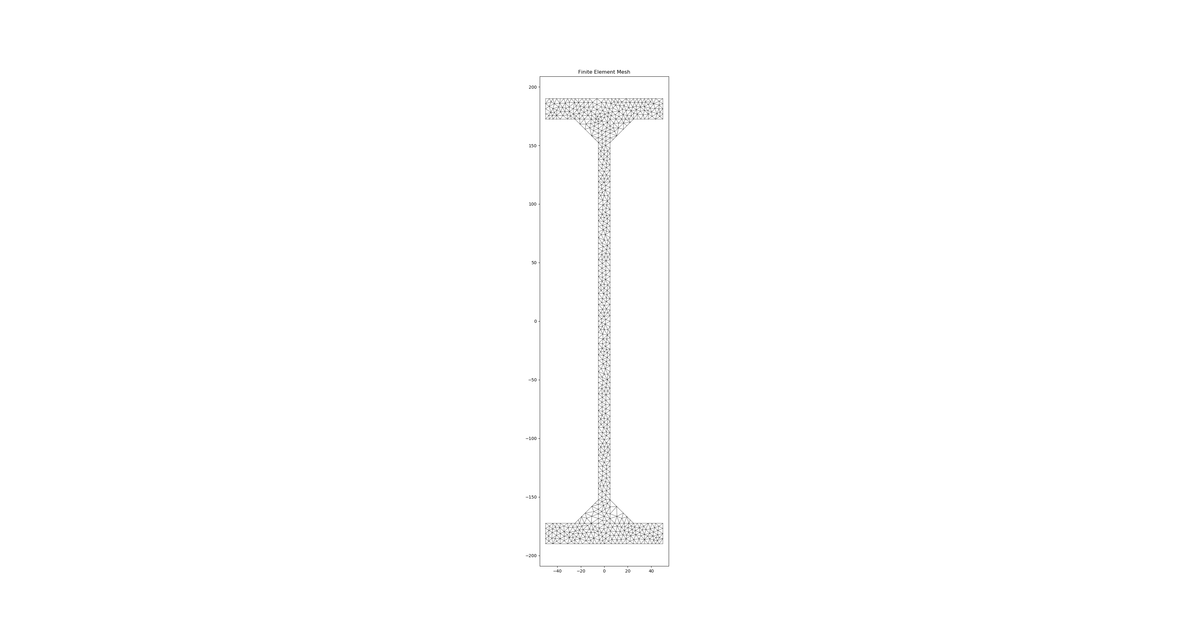
Desktop (please complete the following information):

Additional context Excellent tool by the way!

robbievanleeuwen commented 5 years ago

Hi Agent6-6-6,

When you create a CustomSection, you need to make sure the control point you define is within the region of the CustomSection and not on an edge, as this can confuse the mesh generator. All the built-in sections automatically choose a control point within the section, but the CustomSection class requires user input for the control point. I will update the docs to make this clear as I don't think it's explained well enough - thanks for pointing this out!

I have modified a few lines of your code with the updated control points and a few different mesh sizes to illustrate that the intended result is obtained:

control_points1 = [[weld_leg_size / 3, weld_leg_size / 3]]
control_points2 = [[-weld_leg_size / 3, weld_leg_size / 3]]
control_points3 = [[weld_leg_size / 3, -weld_leg_size / 3]]
control_points4 = [[-weld_leg_size / 3, -weld_leg_size / 3]]

mesh = geometry.create_mesh(mesh_sizes=[100, 5, 10, 2, 1])

Here's a few screenshots illustrating the intended results:

Screen Shot 2019-04-10 at 7 30 56 pm Screen Shot 2019-04-10 at 7 31 09 pm

Also, thanks for the kind words in the additional context :wink:

Let me know if you have any other questions!

Robbie

Agent6-6-6 commented 5 years ago

Thanks for that, am I right in thinking that the control point needs to avoid any holes also? I assume its used as a starting point for the mesh generation so needs to be within the section?

As a feature request is it possible to consider a check to ensure the control point is within the defined section, and halt/cause an exception if its not as a check to what is a manual process of deciding the point.

I guess with some logic it would be possible to guess a location and check to make it automatic (for a simple solid without holes (circle, rectangle) you could find the centroid and check this was within the section or similar and automatically define the control point. But obviously harder for any holes or complicated shapes.

I did observe some odd behaviour putting the control point inside the weld sections, with the shift it seemed to move the control point well below the section. I'll try replicate it again, but the way it seemed to stay with the section was by putting it right on the corner, but this was quite early on in getting the hang of running the code so quite entirely possible I was defining something incorrectly!

Just a general thought also as a suggestion for another advanced example demonstrating calculation efficiency:- I think it would be good to have an example showing for an I section that going to a finer mesh over the entire section isn't entirely warranted for accuracy, using more points around the curve for the root radii drives the mesh smaller in these regions and this results in accuracy where its needed and a much faster calculation overall for the same overall accuracy in the properties. Sort of similar to the example of calculating J with mesh size vs time, I think if you changed the points around the curved portions at a coarse mesh size you will see the same accuracy but much faster calculation time for the same problem! EDIT Actually just qualifying that this might depend on what property you are calculating/interested in, certainly true for some properties.

Agent6-6-6 commented 5 years ago

Two other things while I have your attention :) :-

Any chance of developing a built in routine for a monosymmetric beam (different sized flanges top and bottom) and hence also calculating the corresponding monosymmetry section parameter (beta_x in AS4100/NZS3404).

From NZS3404 image

Note beta_x also required for tee sections

Just a thought, I also noted for symmetric sections where the centroids/shear centers are at '0', that there maybe should be a tolerance on a zero answer and if sufficiently small set the parameter to zero. Reasoning from my perspective is simply when comparing different mesh sizes for example if you compare percentages for all calculated parameters, then the centroids and shear center dimensions can be zero for all intents and purposes but the ratios between can be wildly varying but still small as 0.000001mm vs 0.0000001mm is 10x, but still very close to zero obviously. This throws these ratio comparisions all over the place i.e all other parameters with a tangible value >0 are close to 1x vs 10x, and this doesn't really represent the error being very minute.

robbievanleeuwen commented 5 years ago

Yes the control point needs to be within the meshing region and therefore cannot be located within a hole. It is used by the meshing algorithm (not developed by me - see triangle in meshpy) to define the regions.

The CustomSection can have multiple regions, e.g. multiple areas with different mesh sizes and control points, with multiple hole locations. While it would be nice to implement a check I put this one in the too hard basket as the complexity of the task pretty quickly spirals out of control. There may be a simple solution, but I couldn't come up with one! This is only a problem for CustomSections so I would recommend the user checks the control points locations with a plot_geometry call. An incorrectly placed control point will only affect the meshing so I would also recommend checking the mesh with a plot_mesh call. Both probably good practice when undertaking a finite element analysis - junk in junk out :wink:.

If you can replicate the strange control point behaviour that would be great - the shift is the last function called when creating a section so should shift everything the same distance, but if there's a bug in there I'd like to find out!

Feature requests:

  1. Added the example to the to-do list.
  2. Added the monosymmetric I-beam to the to-do list.
  3. Added the mono-symmetry parameter to the to-do list.
  4. Rounding of results - I think this is more related to a discussion between relative error vs. absolute error and is more of a post-processing feature. I would prefer to leave the output of results as is rather than rounding within my program, which in a way makes the program more of a black box. If users want to post-process the numbers they can easily do so within their own script. Note that in the display_results function, you can format the results in any way you want by specifying a format string.

Robbie

robbievanleeuwen commented 5 years ago

Any chance of developing a built in routine for a monosymmetric beam (different sized flanges top and bottom) and hence also calculating the corresponding monosymmetry section parameter (beta_x in AS4100/NZS3404).

From NZS3404 image

Note beta_x also required for tee sections

Do you have any results that I can validate the monosymmetry parameters against?

Agent6-6-6 commented 5 years ago

I'll take a look at what I did to see the weird control point thing and try replicate it.

Regarding your point 4, yeah post processing the result is probably better. That's what I was currently doing. Reality is you can get to the typical accuracy of ~3 significant figures in published design section properties tables pretty easily, so having machine level accuracy is a little academic.

I'll have a look tomorrow and see if I have any example calculations for the beta_x factor. For practical purposes for design I'd just use the simplified equation in the code typically, but evaluating the integral should be fairly similar to see if you are in the ballpark.

Have you thought about putting in calculations for effective section moduli for bending or effective area for axial loading taking into account plate slenderness limits? Obviously this would be getting into code specific areas as local slenderness limits would differ depending on code. But I guess its these parameters that are of the most interest for practical design. Probably falls into the post processing arena as fairly easy to setup using your results in a post processing module (I'm working through this now for my own experimentation to NZ steel code).

Agent6-6-6 commented 5 years ago

Referring to #4 - have a look at page 9 of this document, it expands the integral (minus the root radii contribution) and should be good for comparing results if you are evaluating the integral directly using numerical methods!

Edit - I'd add that that from memory the two answers should be the same number but opposite signs (largest flange in compression is positive, vs smallest flange in compression being negative). So potentially only need to evaluate the integral once.

Agent6-6-6 commented 5 years ago

Hi Robbie

Also see this document, in the UK the derivation given in BS5950 has the same integral defined as part of the mono-symmetry index for unequal angles and there are published value in section properties for this index. So you can back calculate out the integral part from the published values knowing t, I_u and v_0 and compare based on your finite element derivation for the integral. Guessing that should be sufficient to check your results are in line with expectations.

normanrichardson commented 5 years ago

Hi Robbie and Agent6-6-6,

The monosymmetric factor seems to appear in many places when considering lateral torsional buckling. I am still coming to terms with this factor, it appears to be calculated with respect to the axis of bending. It also appears that the designer has to decide from the orientation of the moment if the factor is increasing or decreasing the capacity.

In the American aluminum design manual (ADM2015) I've seen it in two sections "F.4.2.5 Any shape" and "F.5.2 Bending Single Angles About Principal Axes".

In the Canadian steel manual I've seen it in CSA S16-09 13.6(e) "Bending - Laterally unsupported members" where it is referred to as the asymmetry factor.

In the American steel manual, I've seen it in AISC 360-10 F10.2 "single angles" part (ii) for bending about the major principle axis of unequal leg angles. In this manual it is called the "section property for unequal leg angles".

I suppose I want to iterate that it would be very valuable to have it calculated for general shapes, as it is not only typical shapes that need this section property. There are tables for L sections which I provide below. The software shapebuilder v9 also calculates this value for general shapes and could be used as "validation" for more complex shapes.

Here is a reference from ADM2015: image image

Here is the L section table from ADM2015: image image image image

Agent6-6-6 commented 5 years ago

Hi Normanrichardson,

I seem to remember the factor should calculate out as a negative value when a mono-symmetric section has the smallest flange in compression, i.e. more susceptible to lateral torsional buckling. Similarly the factor is positive when the largest flange is in compression, i.e. less susceptible to lateral torsional buckling. This overall effect on capacity is fairly obvious to see when you look at the form of the LTB equation in the Australian and New Zealand steel standards where the factor is used directly (rather than being used/incorporated in a slightly different form in some other standards (like Eurocode)). Negative reduces the reference buckling moment, positive increases it.

i.e. image

When beta_x = 0 for the case of symmetric sections, then this form of the equation reduces to the following which is your classical LTB equation. image

Out of interest I watched a recent AISC video where they went through deriving the equation, if its of any interest here is the link

Robbie, I tried to recreate the issue I was seeing with the control points being offset. I've come to the conclusion it must have been user error on my part as have not been able to replicate it!

normanrichardson commented 5 years ago

Thanks for this, will give it a listen. I've only been through the nz code once, and it honestly was one of the clearer ones ... par the unfortunate choice of notation for the elastic section modulus and plastic section modulus!

robbievanleeuwen commented 5 years ago

Hi Gents,

Have incorporated the monosymmetric parameter calculation when calculating the warping properties in the commit d09685c. Will add it to the next release when I'm satisfied it's working as expected.

Have done a few tests with the above info and the numbers seem to be relatively close. Get an almost exact match with the the webless I-beam example from the Trahair paper and a less close match, but still within 10% with the British examples (never sure if there are some simplifications in these tabulated values...) Would be happy to have a look at any test cases/validation you guys do as well!

Let me know if you find any errors or have any questions about the monosymmetry calcalation!

Cheers, Robbie

Agent6-6-6 commented 5 years ago

Hi Robbie

I'll give it a test and compare to some simple hand examples.

One comment though based on reviewing the code and trying a few examples with the new mono-symmetric section generator:-

For each axis there should be a plus and minus value (similar to the elastic moduli) dependent on which flange is in compression (see discussion above), the +/- values come about because of the shear center being of the opposite absolute sign from the elastic centroid for consideration of the section being flipped. plus and minus value should be consistent with the way section is being bent for determining the elastic modulus (for consistent approach). I am assuming the same holds true for any "general" defined section.

If you run an example with the top/bottom flange values being swapped vs original section you should see the same beta value will be reported except the opposite sign. The sign is quite important when using the value to calculate the moment capacity of a mono-symmetric section! For example manually flipping a monosymmetric I section gives the following results for beta values:- 152.77800483318694 2.3494952064576823e-06 152.77800483318694 2.3494952064576823e-06 & -152.77799891389088 -1.4679902385065195e-06 -152.77799891389088 -1.4679902385065195e-06

robbievanleeuwen commented 5 years ago

Hi Agent6-6-6,

Thanks for pointing that out, I didn't realise the integration axis and hence the shear centre sign flips depending on which flange is in compression. Have implemented this now in the latest commit 90f8ffb.

Happy to hear your thoughts :smile:

Robbie

Agent6-6-6 commented 5 years ago

Hi Robbie, the new addition of plus/minus values for beta seems to work as intended.

I've been through a number of sections using IES shapebuilder as a comparison and the values compare very well (fractions of a percent). IES shapebuilder only outputs the beta_x associated with the principle '11' axis though. So you cannot compare the number if you rotate the section or anything.

The other thing worth noting is I found your code a hell of a lot quicker than using shapebuilder for the same max mesh size which is a bonus.

One thing I did note as a sideline comment for anyone following later is the simplification in the AS4100/NZS3404 of beta_x = 0.8d_f*((2Icy/Iy)-1) sometimes doesn't compare that well (its a simplification after all), probably somewhat similar to the differences you noted in comparing some of the tabulated values wghich may not be based on FEA results. The value using the simplification always seemed to come out to a lower absolute value, which interestingly means its potentially conservative in one case (when beta_x is positive), but unconservative the other way round when considering the LTB equation (when beta_x is negative) and the true FEA solution for beta_x.

Many thanks for adding it in as an option.

robbievanleeuwen commented 5 years ago

Thanks - good to hear the performance is working well!

I also found some issues witht eh simplification in the code when trying to validate my results!

Thanks for suggesting this useful addition!

Robbie