ros-drivers / ros2_ouster_drivers

ROS2 Drivers for the Ouster OS-0, OS-1, and OS-2 Lidars
https://ouster.com/
Apache License 2.0
134 stars 79 forks source link

Frame transformations different from Ouster Software Manual #84

Open Gaurav-Kapoor-07 opened 2 years ago

Gaurav-Kapoor-07 commented 2 years ago

Hello I just checked that the frame transformations on the tf_static topic are different from the transformations given in the Ouster Software Manual. This is the output if the /tf_static topic which is published just once when we start this driver -

transforms:

When I visualized the data in RViz I saw that the laser_sensor frame is rotated by 180 degrees from the RViz axes. The laser_data_frame in RViz with respect to the real Ouster 0S1-128 Sensor was like this - IMG_20210929_160351 
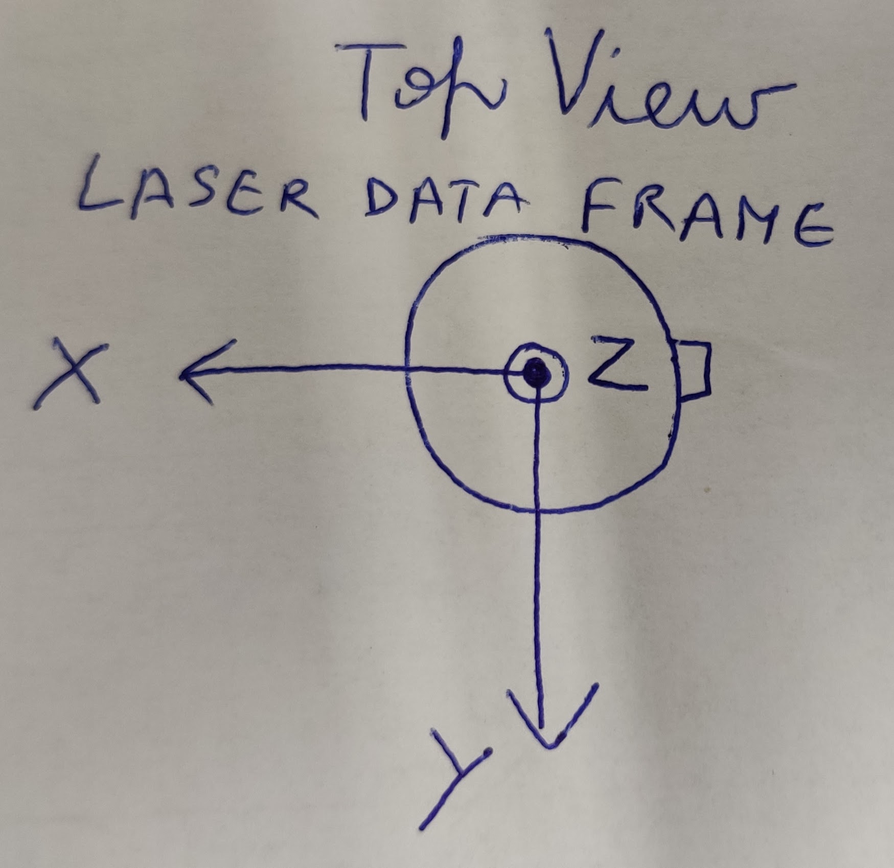
Which is completely different from the frame transformations given in the manual. So I want to know the correct transformations of the laser_data_frame and imu_data_frame with respect to the laser_sensor_frame and also the correct position and orientation of the laser_sensor_frame with respect to the real Ouster Sensor.

Thanks.

Best regards Gaurav

mnissov commented 2 years ago

I think the rotation part is actually correct, in the software manual they define three frames: sensor, lidar, and IMU. I imagine these correspond to the laser_sensor_frame, laser_data_frame, and imu_data_frame respectively.

That being said, there is an error in the translation portion of the transformations as the sensors each carry a certain vertial offset between frames. This is illustrated here image image

Gaurav-Kapoor-07 commented 2 years ago

@mnissov You are right. The rotation part is correct but relatively. I realized by visualizing the data in Rviz2 that the laser_data_frame is 180 degrees to the lidar frame in the software manual but the translation between them is 0, 0 , 0. In software manual the x axis of the lidar frame points to the backwards towards the external connector but in this driver it points to the front(as shown in the hand drawn image by me above). Then other frames relative to the laser_data_frame would be correct.

mnissov commented 2 years ago

I see what you mean, following the naming in the parameter yaml file of sensor_frame, laser_frame, and imu_frame:

If I set the sensor_frame according to the manual, positive x pointing opposite to connection, then the /points published with frame_id laser_frame are rotated 180deg in rviz, with respect to the same object from a velodyne LIDAR.

I suppose the quickest solution is just to rotate the sensor_frame by 180deg in my urdf file, but that would seem sloppy.

Are we misunderstanding something or is this actually an error? @SteveMacenski

Edit: I've just checked the same setup with the ros1 package from ouster_ros of ouster_example. The behavior is mirrored, approaching the lidar from the connector side shows my hand in rviz2 on the positive and negative x-axis in the ros2 and ros1 versions. In addition, the ros1 version be default reads and includes the relevant translations.

So it would seem as though there is something missing?

This was done in rviz using the sensor_frame as the fixed_frame.

Gaurav-Kapoor-07 commented 2 years ago

@mnissov Yes this is what I did in my application. I rotated the laser_sensor_frame by 180 degrees. But then we have to offset the laser_sensor_frame by +36.18 mm as the laser_sensor_frame and laser_data_frame are at the same translational position (in this ROS2 Ouster driver). This is because the LaserScan messages in the /scan topic are the 0 degrees beam elevation angle of the lidar and they are in the laser_data_frame which cannot be at the same height of laser_sensor_frame as the laser_sensor_frame is at the base of the lidar sensor.

mnissov commented 2 years ago

@mnissov Yes this is what I did in my application. I rotated the laser_sensor_frame by 180 degrees. But then we have to offset the laser_sensor_frame by +36.18 mm as the laser_sensor_frame and laser_data_frame are at the same translational position (in this ROS2 Ouster driver). This is because the LaserScan messages in the /scan topic are the 0 degrees beam elevation angle of the lidar and they are in the laser_data_frame which cannot be at the same height of laser_sensor_frame as the laser_sensor_frame is at the base of the lidar sensor.

Hopefully this could be integrated into the package though, as far as I can see the package reads this metadata, the transformations, from the sensor so I can't quite see why it shouldn't be correct. Given that the same sensor works fine w/ the ros1 package which presumably does the same.

Edit: Did you rotate by adding a static transform broadcaster?

Gaurav-Kapoor-07 commented 2 years ago

Actually I had to give the transformation from the base_link of the robot to the laser_sensor frame.There it self I rotated the laser_sensor frame by 180 degrees and added the offset of +36.18 mm. So that I am giving as a static transform in my URDF. I also then used Google Cartographer to make the 3D SLAM with 3D lidar, IMU and odometry and the results were very well. When I did not rotate the laser_sensor_frame by 180 degrees my SLAM results were horrible.

mnissov commented 2 years ago

Maybe it's a problem with how the transformation is applied, looking at the tf_echo between the ros1 and ros2 package it seems like the rotations more or less match.

image

goksanisil23 commented 2 years ago

I'm coincidentally facing the same problem, and the main issue is that the translation values between the sensor and laser/imu frames are omitted in ROS2 drivers (as it can be seen from your screenshot too)

goksanisil23 commented 2 years ago

I have tracked the problem to https://github.com/ros-drivers/ros2_ouster_drivers/blob/593dc2bbde252e14658b1ae405f536fab0dd9ffa/ros2_ouster/include/ros2_ouster/conversions.hpp#L107

I believe the lines should be changed as the following:

image

@SteveMacenski do you agree?

mnissov commented 2 years ago

@goksanisil23 this fixes the translation, however I still believe the rotation has something strange

I've placed a chair next to the connector side of the lidar, this means in lidar_frame it should be on the positive side of the x axis and in sensor_frame on the negative. At least according to what I have read in the software manual.

Doing so and monitoring using the sensor frame and lidar frame as baselink shows that it is in fact the opposite, so I think there should still be a mismatch somewhere.

image image

Edit: echoing the points shows they are expressed in lidar_frame. It's weird, it's as if the scan was taken CW instead of CCW or something.

Aposhian commented 1 year ago

For reference, it looks like there is a bug in this driver where the driver stamps pointclouds with the lidar_frame, but it actually applies the transformation to put them in the sensor frame. See resolution at: https://github.com/ouster-lidar/ouster-ros/issues/33

ga58lar commented 5 months ago

@goksanisil23 thanks a lot for the fix!