shankar1729 / jdftx

JDFTx: software for joint density functional theory
http://jdftx.org
79 stars 49 forks source link

Small teeth on surface energy vs. slab thickness graph #308

Closed ximik69 closed 7 months ago

ximik69 commented 7 months ago

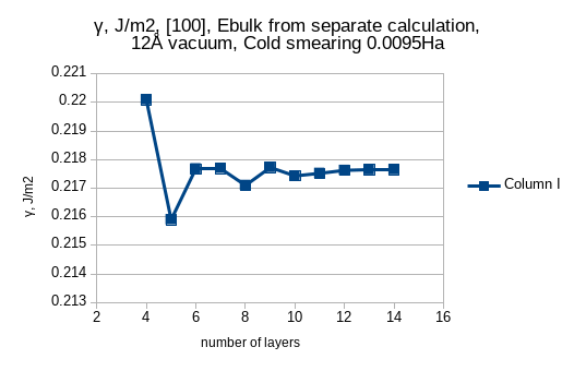
Hello dear Shankar, I have encountered small teeth about 0.01 J/m2 while trying to find convergence of surface energy of Na {100} as a function of slab thickness. For me it is quite ok, because surface energy of Na {100} is 0.22J/m2 and I reproduce it. But how can I get rid of these teeth?

My workflow was the following:

  1. optimize lattice geometry of conventional cell of bulk Na
  2. construct slabs {100} of different thickness using optimized geometry of bulk+10A vacuum I used python scripts using pymatgen+ase functions for that
  3. run ionic minimize on constructed slabs w/o any fixed Na atoms
  4. calculate surface energy in three ways: a) gamma=(Eslab-ZEbulk)/(2S), taking Ebulk from calculation (1) https://github.com/ximik69/JDFTx_debug_output/blob/main/gamma_Ebulk_from_separate%20calc.png b)fit Eslab=f(n layers), then Ebulk is slope, and I calculate gamma according to the formula above https://github.com/ximik69/JDFTx_debug_output/blob/main/gamma_Ebulk_from_fit.png c)calculate gamma= [Eslab(n)-(Eslab(n)-Eslab(n-1))*n]/(2S) using energies of slabs having 1atom difference of thicknesses https://github.com/ximik69/JDFTx_debug_output/blob/main/gamma_Ebulk_from_consecutive_layers.png

The convergence in case 4a is not visible, in case 4b there is some tendency towards convergence and in case 4c no convergence is seen. In case 4a some linear slope is due to small difference between Ebulk from separate calculation and Ebulk from consecutive increase of slab thickness. This is mitigated in case 4b. I have deliberately chosen 8 layers as some tradeoff between accuracy and speed.

ximik69 commented 7 months ago

My settings are - SG15 pp, 50Ha cutoff, 1E-8Ha energy diff threshold for elec-minimize,

1E-7Ha energy diff threshold for ionic-minimize, knormThreshold 1e-5. Thus the structures are converged quite well.

I optimize only atomic positions and parameters of the unit cell are fixed.

I use

coulomb-interaction Slab 001
coulomb-truncation-embed 0 0 0.5

in order to mitigate interactions between slabs. But I see teeth on the surface energy vs. slab thickness plot.

ximik69 commented 7 months ago

Then I tried to converge different vacuum thickness from 10 to 32A. It was not ideal due to some decrease of energy for the thickest vacuum layer. https://github.com/ximik69/JDFTx_debug_output/blob/main/gamma_vacuum_convergence.png

ximik69 commented 7 months ago

Different thicknesses of vacuum did not change anything regardless of being commensurate or not with the unit cell of Na . I tried switching off symmetry without any qualitative changes.

ximik69 commented 7 months ago

I'll post the output tomorrow, cuz I couldnt use neither pastebin nor alternatives.

Upd: I created github repo and posted there the initial structures and JDFTx output for some of the slabs. https://github.com/ximik69/JDFTx_debug_output/tree/main/Na_100_slab_debug

The directory names are the following:

[number of atomic layers]_vacuum_[vacuum width above and below the slab]

.

Actually 13_vacuum_12_opt means 13 layers, having 12 Angstr of vacuum above and below the slab=2*12=24 Angstr of vacuum between layers.

Dear Shankar, what did I do wrong and how to converge layer thickness and vacuum thickness for surface energy correctly?

Best wishes, Igor.

shankar1729 commented 7 months ago

Your energy cutoff (10 Eh) seems too small for an Na pseudopotential with semicore electrons. You may need 30 - 40 Eh for the SG15 pseudos you used, and ~ 20 Eh for GBRV. This could be introducing geometry convergence issues.

Everything else looks fine to me. Also, note that metal surface energies can exhibit such oscillations with layer number, due to effects related to Friedel oscillations. So, this could still be a physical effect, but you need to converge plane-wave cutoff first.

Best, Shankar

ximik69 commented 7 months ago

Dear Shankar, thank you for your reply. Actually I use 50Ha cutoff for the geometry optimization and final calculations of energy.

10Ha cutoff at the very beginning is from the way I converge electronic minimization. I converge at 10Ha, then read wfns from it and converge at 20Ha, then converge at 30, 40 and finally at 50Ha.

This approach is advantageous if I need 100-200 or more iterations for elec minimize for slowly converging functional, especially for scan or tpss. I have almost the same number of total iterations by this stepwise convergence or just at final cutoff but it speeds things up. It works well for slow convergence but slows down considerably for fast convergence like Si.

Best wishes, Igor.

shankar1729 commented 7 months ago

I see: I missed the higher cutoffs later in the logs. In that case, I fall back to my Friedel oscillation explanation. In particular, you also reduced the smearing in the final calculations, which makes these oscillations more pronounced.

Try running the final calculations with a higher smearing than room temperature. Your 11 x 11 x 1 k-point folding is sufficient for ~ 0.01 Eh smearing you started with, but not for the 0.001 Eh smearing. You'd need almost 10x the k-point folding to converge fully at that lower smearing. This might be the reason you are not getting the same bulk energy from the fit and the separate calculation too.

Also, while this bootstrapping approach may save some time, I'd advise having such a complicated workflow in production calculations. Maybe a 1-step increase of cutoff should be okay, say from 20 to 40 Ha or so, but it would be better to avoid very low cutoff starting points in case it gets you trapped in a wrong solution. (That doesn't seem to be the case here.)

Best, Shankar

ximik69 commented 7 months ago

Dear Shankar, thanks a lot for your explanation. I started optimization of slabs with 0.01 Eh smearing and at the beginning it gives much smoother plot if I use free energy F from script listEnergy. If I use Etot, the plot has the teeth, similar to the previous one. I'll see the final data and then write you more in detail.

I have a question. I've read somewhere in your posts here on github, that one should use F if one has bigger smearing if I understood that correctly. But what is the correct workflow for calculations of some properties (energies of reactions, surface energy etc), if I have 0.01 Eh smearing (=3000K) for the room temperature 300K? Which values should I use for that?

Best wishes, Igor.

shankar1729 commented 7 months ago

Yes, always use F as it is the variational free energy. If you want to reduce the higher TS contribution present due to a higher smearing, use Cold/MP1 smearing instead of Fermi/Gauss options. These are intended to reproduce T=0 energies from a finite smearing case based on specific approximations of the DOS vs energy variation.

Best, Shankar

ximik69 commented 7 months ago

Dear Shankar, thank you for the explanation. I tried some dirty hack - ionic-optimize of the previously mentioned slabs w/o reoptimized cell params. It gave much smaller oscillations but with tendency to growth. Thus progress is evident.

I'll show you later the correctly made results with cold smearing 0.0095Ha, so as unit cell was optimized and its parameters given to slabs and their ionic positions optimized.

Best wishes, Igor.

ximik69 commented 7 months ago

Hi dear Shankar, I successfully reached convergence! Thank you!

image

image

image

image

image

What I did was - I changed smearing to Cold 0.0095Ha, then optimized lattice of Na. Then created slabs with these parameters of the unit cell and optimized their atomic positions with fixed parameters of the unit cell.

The results are successful.

Best wishes, Igor.

shankar1729 commented 7 months ago

Great, that looks reasonable: thanks for the update!