skywodd / pcf8574_arduino_library

PCF8574 / PCF8575 Arduino library (version 2.0)
88 stars 56 forks source link

Problem with digitalRead() function #3

Closed FernandoGarcia closed 5 years ago

FernandoGarcia commented 9 years ago

Hi! I have problem to use the function digitalRead() it returns always LOW. I'm using two ways to check the status without success. See the code:

# include <Wire.h>    // Required for I2C communication
# include <PCF8575.h> // Required for PCF8575

/* PCF8575 instance */
PCF8575 expander;

void setup() {

  Serial.begin(115200);

  /* Start I2C bus and PCF8575 instance */
  expander.begin(0x20);
  for (byte i = 0; i < 16; i++)
  {
    expander.pinMode(i, OUTPUT);
  }
}

void loop() {

  for (byte i = 0; i < 16; i++)
  {
    expander.digitalWrite(i, 1);
  }

  for (byte i = 0; i < 16; i++)
  {
    Serial.println(expander.digitalRead(i) ? "HIGH" : "LOW");
  }
  delay(5000);
  for (byte i = 0; i < 16; i++)
  {
    expander.digitalWrite(i, 0);
  }
  for (byte i = 0; i < 16; i++)
  {
    Serial.println(expander.digitalRead(i));
  }
  delay(5000);
}

Can you check if this function works for you and if my code is wrong? Best regards.

skywodd commented 
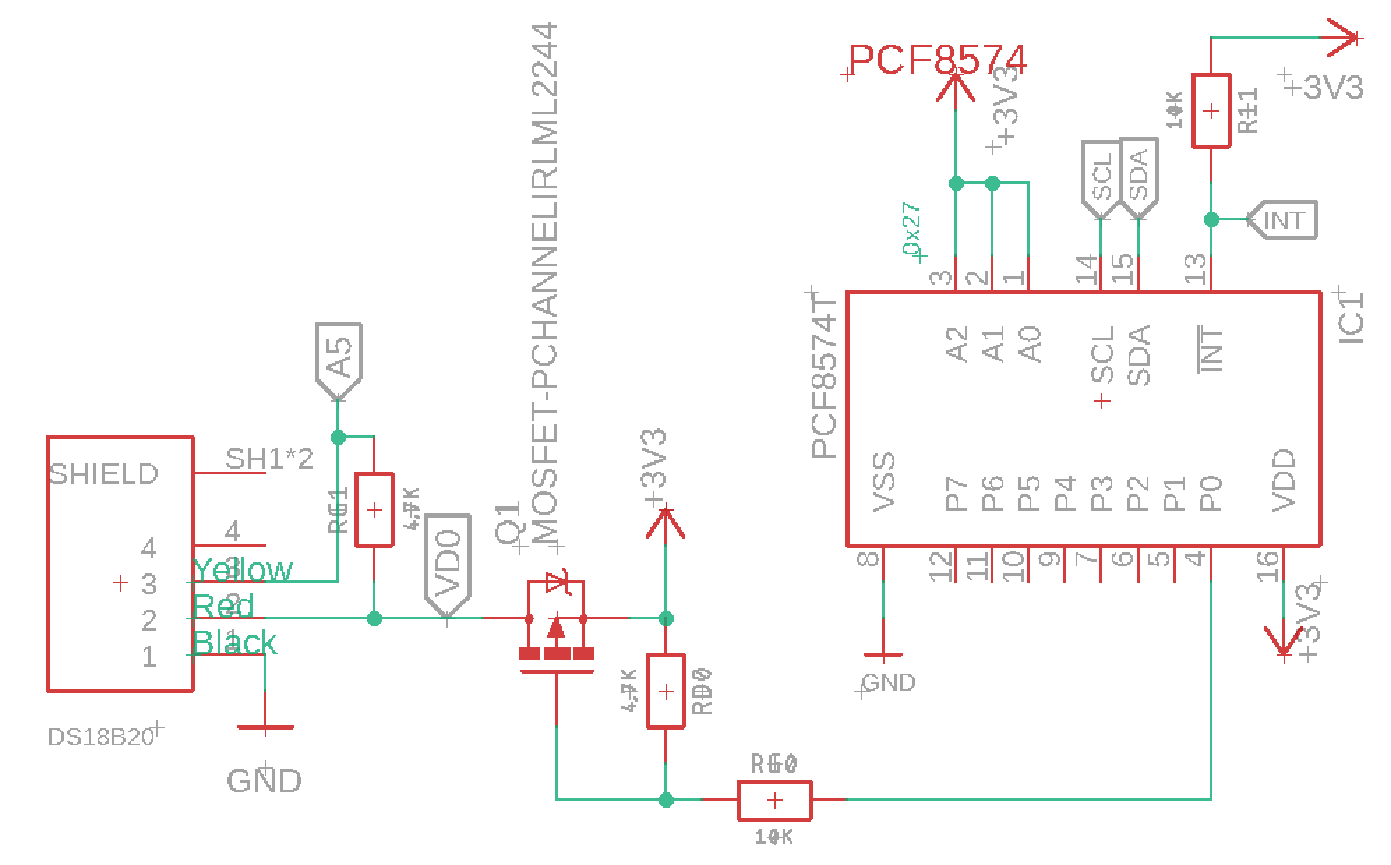
9 years ago

Write and read actions goes to the same data buffer in the PCF857x chip. So reading from an output pin should return the last value written to this pin, if the pin is not being forced to another signal level by an external signal.

For me, by reading your code, the first loop of digitalRead should always return 1 because you are writing 1 to the pin before, and the second loop of digitalRead should always return 0 because you are writing 0 to the pin before.

FernandoGarcia commented 9 years ago

Hi!

I have always this result:

LOW LOW LOW LOW LOW LOW LOW LOW LOW LOW LOW LOW LOW LOW LOW LOW 0 0 0 0 0 0 0 0 0 0 0 0 0 0 0 0

Can you test it please? Best regards.

alsacian commented 7 years ago

Swapp : "LOW":"HIGH"

FernandoGarcia commented 7 years ago

Will return always "HIGH".

FernandoGarcia commented 6 years ago

Just to make sure it was not my error I have changed the test code.

As you can see I'm writing 1 but the function returns always LOW.

error

francescolavra commented 6 years ago

When the code executes expander.digitalWrite(i, 1), it's actually configuring pin i as input (a PCF8575 pin cannot be configured as output with high value); if a pin is configured as input and is not connected to anything, the input value you read from it could be either high or low (PCF8575 pins configured as inputs don't have internal pull-up or pull-down resistors). So if you expect to read 1 from a pin on which you previously called digitalWrite() with value 1, you should connect an external pull-up resistor to the pin.

pierrot10 commented 5 years ago

Good day, I am confused with that discussion because I have the same issue than fernando garcia. If I check the example I defined an output as the follwoing and I put it HIGH a pin as the follwoing

Here it show how to read a INPUT status So could be not read a OUTPUT status as well

Personally, I only use pin 1 to 6 and I test this

      expander.pinMode(1,OUTPUT);
      expander.pinMode(2,OUTPUT);
      expander.pinMode(3,OUTPUT);
      expander.pinMode(4,OUTPUT);
      expander.pinMode(5,OUTPUT);
      expander.pinMode(6,OUTPUT);
     for(int p=1; p<7;p++){
      expander.digitalWrite(p,HIGH);
      delay(50);
      Serial.print(F("\t.P")); Serial.print(p); Serial.print(F(":"));
      Serial.println(expander.digitalRead(p) ? "HIGH" : "LOW");
      delay(50);
    }

and it display my only the pin 4,5,6 HIGH

.P1:LOW .P2:LOW .P3:LOW .P4:HIGH .P5:HIGH .P6:HIGH

Could you tell me why PI thu P3 are LOW and how can I make sure it goes UP. I absolutely need it to be HIGH to power 3 tensiometric moisture sensors (each pin for each sensor and not all at the same time) The sensors are not connected during my test. P4 will power and soil temperature sensor for some ms sec P5 and P6 are used for led.

Thank a lot

pierrot10 commented 5 years ago

Why the way, do you know if that library is fully compatible with SAMD21 ARM cortex micro-controller? I has to comment that following line to eliminate a lot of errors due to PCInt.h

I would like to add a separate question. P1, P2 and P3 are powering a tensiometric moisture sensor and the value are not correct since I powered it with a PCF8574. Do you know what the max output voltage and current of P1,P2 and P3?

Because of this issue, I really need to monitor the time P1, P2 and P3 are HIGH. It should be HIGH 1 to 3 sec.

Thanks a lot. Regards

francescolavra commented 5 years ago

Again, a PCF8574 pin cannot be configured as output with high value, so if you need to power your moisture sensors via PCF8574 you can't do that directly with PCF8574 but you need additional circuitry, e.g. MOSFETs (one for each PCF8574 pin). The maximum output current is 25 mA per pin, but only when a pin is configured as LOW output.

As for the compatibility of the library with SAMD21, the answer is no; as you noticed, the part that deals with interrupts doesn't build for SAMD21, because it uses hardware peripherals specific to AVR chips.

pierrot10 commented 5 years ago

@francescolavra Dear Franscesco. Thank again for your reply. Than I would be able to power my sensor when P1 is LOW or using a circuit similar to this

francescolavra commented 5 years ago

As far as I can see, the circuit you referenced won't work, because in order to power the sensor you would need to actively drive Q1 with a high logic level, which you can't do with PCF8574. Instead, you could remove Q1 (along with R32 and R33) altogether, and connect P0 directly to R38. This way, when you set P0 to a low output value (which you can do), Q2 is activated and powers the sensor.

pierrot10 commented 5 years ago

Good day Francescolavra. However, does the PCF8574 can close a MOSFET, when P1 is HIGH. Following this schema If I connect P1 to gate, VCC can power a LMC555 with 3.3V? Thanks!

francescolavra commented 5 years ago

No, PCF8574 can't close a MOSFET when P1 is high, it can only close a MOSFET when you drive its output pin low. So in your schema you would be able to power the LMC555 by connecting P1 to the gate of Q7 (instead of Q6) and driving P1 low.

FernandoGarcia commented 5 years ago

This library works as expected.

https://github.com/maxint-rd/mxUnifiedPCF8574

pierrot10 commented 3 years ago

Again, a PCF8574 pin cannot be configured as output with high value, so if you need to power your moisture sensors via PCF8574 you can't do that directly with PCF8574 but you need additional circuitry, e.g. MOSFETs (one for each PCF8574 pin). The maximum output current is 25 mA per pin, but only when a pin is configured as LOW output.

As for the compatibility of the library with SAMD21, the answer is no; as you noticed, the part that deals with interrupts doesn't build for SAMD21, because it uses hardware peripherals specific to AVR chips.

Dear Francesco, Last time we spoke about how to power the tensioetric sensor. I use a MOSFET (IRLML2244) to power it and the pin output of the PCF874 close the MOSFET when the output is low, and my sensor is power.

I also power a DS18B20 without the MOSFET as the following schema because the DS18B20 does. not need a lot of power, and I thought it was enough with the PCF8574 output. It has been working for a long time, since the DS18B20 break and I replace with a new one. Since the measure are not exact. For example, my flat temperature is abour 20°C and the sensor print me 30°C and the seoncd 37°C.

I do not understand why I have this issue but I wonder if the DS18B20 sensor are not well powered by the PCF8574. And I wonder if I would better add a MOFSET between the DS18B20 and the PCF8574 output.

I believe it would be better, as it was previously working, I would like to ask your point of view regarding. I wonder why, it worked before? (or may be I thougt it was working :) )

Many thanks

francescolavra commented 3 years ago

@pierrot10 in your schema I can't see how the DS18B20 is connected to the PCF8574, anyway the DS18B20 needs a good amount of power to do a temperature measurement, so I don't think it can work if connected to the PCF8574 only

pierrot10 commented 3 years ago

@francescolavra Dear Francesco, thank for your reply. I just have a try with PO of the PCF8574. I also have a MOSFTE IRLML2244TRPBF follwoing this new schema. Regarding the DS18B20, it has tree wire: RED, BLACK, YELLOW.

(Be careful about my confusing naming :) ) P_0 (of the schema) is connected to pin 4 of PCF8574 (P0) P0 (of the schema) is connected to wire RED of the DS18B20

The wire BLACK is connected to GND The wire YELLOW is connected to A5 of my micro-controller with a 4K7 pullup resistance.

First try: I disconnected the DS18B20. When pin 4 of the PCF8574 (P0) is LOW, there is 3.2V, at the connected where the RED wire is connected When pin 4 of the PCF8574 (P0) is HIGH, there is 0V at the connected where the RED wire is connected THAT'S WORK.

second try: I connected the DS18B20 to the connector When pin 4 of the PCF8574 (P0) is LOW, there is 1.6V, at the connected where the RED wire is connected

That's not normal because I should measure 3.2V

I powered off my circuit and I connected my DS18B20 to its connected, and I controlled there is bad connection, but RED; YELLO and BLACK wires are isolated (there is no bad connection between them, oof).

I wonder why, my DS18B20 drop the voltage to 1.6V?????

Would it be possible that RED wire is not the VCC? YELLOW wire is not the signal? I know some time the DS18B20 do not have the same color wire.

Do you an idea why I have this issue if you have an experience with DS18B20?

The DS19B20 is connected : RED wire to P4. GNG to GND and signal to A5. P4 is the pin 4 of the PCF8574. As the DS18B20 is a wet soil, I do not want to keep it power any time. That the reason why P4 will power it when a measure is needed and the power it off until next measure. I am going to try to use a MOSFET IRLML2244TRPBF to see the difference. In that way, the DS18B20 will be power with 3V3 from the SPX3819-3.3 which low the voltage from the 3.7V lithium battery to 3.3V

francescolavra commented 3 years ago

I don't know the color schema used for the wires coming out of your DS18B20 shield, I suspect the 3 signals are not what you think they are. Anyway, we are getting off topic here...