 dmeehl
commented
11 years ago
dmeehl
commented
11 years ago You can find the stl file here:
Closed dmeehl closed 10 years ago
dmeehl
commented
11 years ago You can find the stl file here:
 alranel
commented
11 years ago
alranel
commented
11 years ago Yes, this is a known issue with the current medial axis implementation. A new implementation is being worked on which should address all the pending issues with thin walls, often referred here in GitHub issues as medial-MGD. This particular issue was already reported in other issues (#505 and many others), I'll leave this open as an additional test case for now.
dmeehl
commented
11 years ago Fantastic. Thank you.
How far along is the medial-mgd branch? In the 0.9.8 release notes: "Also, important work is sitting in three branches waiting to be merged right after this release (it wasn't tested enough for inclusion in this one)" Is one of those branches medial-mgd?
 mesheldrake
commented
11 years ago
mesheldrake
commented
11 years ago Could you re-post the config file? The link doesn't work anymore.
I'm looking at this model now, but I want to make a good comparison between my results and your photos.
dmeehl
commented
11 years ago mesheldrake
commented
11 years ago Thanks for the config and this good simple test case.
Here's the kind of output I'm working on (filament shown too thin, to show paths better):
The thin wall path and outer perimeter are continuous as much as possible.
Here's the complete G code generated using the config you provided: acme adapter sample gcode
Scrolling through the layers in the gcode preview, you can see that we can alternate which way the path turns as it goes from thin wall into the perimeter, which should make all the joints/seams have the same mechanical properties.
mesheldrake
commented
11 years ago The latest version of the medial-thinwall branch is now up. Give it a try with your ACME nut.
I'm curious how the seams will come out. I printed one with a not-quite-calibrated setup and it was a bit blobby all over, but solid.
Yours should look better. Hope you'll post a photo.
dmeehl
commented
11 years ago Seems I'm having trouble getting that branch to build. Here's the output from my sudo perl Build.PL (and subsequent attempt to run slic3r in case that helps). Ideas?
alranel
commented
11 years ago @dmeehl, type sudo cpan Math::Geometry::Delaunay
(@mesheldrake, mind to add it to Build.PL in that branch? I would do it but I'd rather not touch that branch while you're working on it)
dmeehl
commented
11 years ago This looks fixed. Great work! I've attached some photos of a print. If I had to complain about something it would be that the perimeter's endpoint doesnt quite make it back to the start point, which leaves a little indent. You can see this in the 2nd photo (yellow arrow). This problem is not new to this branch. Pretty sure that isnt related to thin walls either. But anyway, this is great. Thanks so much.


dmeehl
commented
11 years ago Here's another photo. You can see that the line doesn't quite make it back to the thin wall before making it's final move toward the center of the model. This leaves a little hook at the end.

alranel
commented
11 years ago Nice!
dmeehl
commented
11 years ago By the way, I've had this branch crash on me a few times. Should I be reporting the crashes? Or is this branch still so beta that I should just ignore it until it becomes more stable?
mesheldrake
commented
11 years ago @dmeehl about the gap at the end: I added some trimming there without checking to see if the path I'm making might get trimmed again down stream. Either I'm trimming too much, or we're double trimming. Will look into it of course.
Thanks for the photo confirmation here.
I'm not getting crashes, but I'm not testing a wide variety of models yet either, so a crash report with model and config would definitely be helpful.
mesheldrake
commented
11 years ago @dmeehl - see if commit 12d7c2d5d4c850ef7521b5521b0981f257d70cf9 for the crash report in #995 fixes your crashes too.
dmeehl
commented
11 years ago about the gap at the end: I added some trimming there without checking to see if the path I'm making might get trimmed again down stream. Either I'm trimming too much, or we're double trimming. Will look into it of course.
@mesheldrake I was wondering if you had a chance to look into this? I've been using this branch with much success, but this is one thing that's been causing me problems.
dmeehl
commented
11 years ago On second look, this could be a different problem. It looks like not only is it stopping the line a bit short, but it's actually creating a small line segment. I'll attach some photos to illustrate. Later, i'll try to come up with a simple test model that reproduces it.
I attached two images which are two subsequent alternating layers. The line segments in red basically shouldnt exist. In the first image, the line segment should continue on to the blue point. In the second, I just shouldnt deviate at all. It should be straight.
Let me know if you want me to file a different issue.


mesheldrake
commented
11 years ago The red paths you point out are just how it works for now. The adjustments to fix that rely on a part of the code that isn't 100% reliable. Also, it doesn't seem like there should be a path across that part of the n, right? I'm guessing the path just decided to turn the wrong way, and connected to the wrong end of another path - sort of a related issue. The basic issue is being able to tell "left" from "right" consistently, I think that part of the "n" is one of the places where we can sometimes get disoriented.
Glad you're getting some good use out of the branch though. I'm reworking some the fundamentals of that code, so the focus isn't currently on refinement of the issues you're seeing. Of course I'm trying to get back to working on those as as soon as possible. It's the main focus right now.
dmeehl
commented
11 years ago Thanks for the reply. No, that part of the path should exist in this font. It should just be a straight line.
dmeehl
commented
11 years ago Hi - Do you have any idea when the medial-thinwall branch will be done and merged back?
dmeehl
commented
11 years ago Hi Mike - Are you guys still working on the medial-thinwall branch? I see there hasn't been a commit in 5 months.
On Sat, Mar 2, 2013 at 10:04 PM, Mike Sheldrake notifications@github.comwrote:
The red paths you point out are just how it works for now. The adjustments to fix that rely on a part of the code that isn't 100% reliable. Also, it doesn't seem like there should be a path across that part of the n, right? I'm guessing the path just decided to turn the wrong way, and connected to the wrong end of another path - sort of a related issue. The basic issue is being able to tell "left" from "right" consistently, I think that part of the "n" is one of the places where we can sometimes get disoriented.
Glad you're getting some good use out of the branch though. I'm reworking some the fundamentals of that code, so the focus isn't currently on refinement of the issues you're seeing. Of course I'm trying to get back to working on those as as soon as possible. It's the main focus right now.
— Reply to this email directly or view it on GitHubhttps://github.com/alexrj/Slic3r/issues/923#issuecomment-14340634 .
alranel
commented
11 years ago @dmeehl, work has moved to the thinwall-bpv branch since then.
mesheldrake
commented
11 years ago And might move again - there's been lots of work with few public commits. Thinwall-bpv should give a good taste of what's coming. Your test object above is still one of the models I'm testing against. If you want to post the stl for that problem case with the letter "n", I'll add that to the mix. The way things work now, it might be feasible to address that kind of issue. (Not that I'll let that hold things up, though.)
dmeehl
commented
11 years ago I actually did find another case which I think may be related. I sliced up a cylinder which mathematically should've sliced to be exactly 4 perimeters, but I cant make that happen. I'll post a test model when I can.
Any idea how far along the branch is (i.e. when it will be merged back and released)? Anything I can do to help?
On Wed, Jul 10, 2013 at 2:00 PM, Mike Sheldrake notifications@github.comwrote:
And might move again - there's been lots of work with few public commits. Thinwall-bpv should give a good taste of what's coming. Your test object above is still one of the models I'm testing against. If you want to post the stl for that problem case with the letter "n", I'll add that to the mix. The way things work now, it might be feasible to address that kind of issue. (Not that I'll let that hold things up, though.)
— Reply to this email directly or view it on GitHubhttps://github.com/alexrj/Slic3r/issues/923#issuecomment-20760798 .
alranel
commented
11 years ago @dmeehl, before posting that case keep in mind two things that might produce your unexpected result:
extrusion width - some overlap, so only multiplying the nominal width value is not enough to predict the number of perimeters in a given thicknessI wanted to point these out, just in case they might affect your test case ;)
mesheldrake
commented
11 years ago It seems really close - but it's seemed that way for four months.
Right now I'm mostly trying to pare down and organize what's working well and trying to get it integrated into the latest dev code so I can get it up here for you to to test.
I'll likely post a note here and on other thinwall issue pages regarding how the new code handles all these test cases. So that should notify you when there's something to test.
 nophead
commented
11 years ago
nophead
commented
11 years ago Why not space the outlines correctly and extrude enough plastic to make them bond rather than overlapping them, The results is the same but the latter is what the user would expect I think.
On 10 July 2013 19:36, Mike Sheldrake notifications@github.com wrote:
It seems really close - but it's seemed that way for four months.
Right now I'm mostly trying to pare down and organize what's working well and trying to get it integrated into the latest dev code so I can get it up here for you to to test.
I'll likely post a note here and on other thinwall issue pages regarding how the new code handles all these test cases. So that should notify you when there's something to test.
— Reply to this email directly or view it on GitHubhttps://github.com/alexrj/Slic3r/issues/923#issuecomment-20763218 .
alranel
commented
11 years ago @nophead, Skeinforge has 'overlap' settings too (defaulting to 15% IIRC). As you say, overlap turns out to be the same exact thing as extruding more plastic. Except that the latter solution will make extrusion width turn out wrong when user measures a single-walled object. Extrusion width = width of a single extrusion.
If we want to add a second loop, we inset by width - some overlap to make them bond.
I think the user experience might benefit from a visualization that shows both width and perimeter spacing to explain the concepts.
nophead
commented
11 years ago AFAIK Skeinforge does not overlap perimeters. It overlaps infill with perimeters. I may be wrong as I rarely use more than one perimeter as it doesn't work very well in Skeinforge when there is no room for the inner loops.
The outer loop should be extruded with the correct plastic to make a single wall the correct width taking into account it is rectangular with rounded ends. Inner loops need a bit more plastic and infill can be 100 % rectangle area.
I think when I retire from selling kits I will have to write my own slicer because none of the open source ones do what I want them to do.
On 10 July 2013 21:13, Alessandro Ranellucci notifications@github.comwrote:
@nophead https://github.com/nophead, Skeinforge has 'overlap' settings too (defaulting to 15% IIRC). As you say, overlap turns out to be the same exact thing as extruding more plastic. Except that the latter solution will make extrusion width turn out wrong when user measures a single-walled object. Extrusion width = width of a single extrusion.
If we want to add a second loop, we inset by width - some overlap to make them bond.
I think the user experience might benefit from a visualization that shows both width and perimeter spacing to explain the concepts.
— Reply to this email directly or view it on GitHubhttps://github.com/alexrj/Slic3r/issues/923#issuecomment-20769728 .
alranel
commented
11 years ago Oh @nophead, you can just change a few lines in lib/Slic3r/Flow.pm, no need to rewrite an entire application. :-)
alranel
commented
11 years ago Just to clarify for readers, when talking about 'overlap' in this context it doesn't mean that a path is actually extruded over a previous one. It means that the centerline of the new path is made slightly closer to the previous line so that when plastic flows to the side it will bond better instead of having just poor contact caused by the rounded shape.
dmeehl
commented
11 years ago I think the perimeter overlap makes sense. Otherwise you'd have the loops only touching at the tangent of the circular ends which would provide almost not adhesion. Obviously the goal is to overlap such that the sum of the two overlaps add up to the same height as the overall loop, so there's no gap/crevice/etc. Whether this is done by increasing extrusion or moving the loops' center points is, I think, a judgement call.
However, what I would like to see happen is slic3r gain the ability to dynamically change the extrusion width when necessary to fill in small gaps. Correct me if I'm wrong, but I think this is part of the goal of the thinwall branches. If you look at the 2nd picture of the letter N above, you can see that to the left and right of the N, there are gaps where the fill does not go. This has been one of the major problems I've run into.
I did more testing regarding the cylinder 'bug' I alluded to. This is what is happening: I created a hollow cylinder whose wall thickness should be exactly 3 extrusion widths, but I can not get slic3r to extrude 3 perimeters. I went as far as to make the outter surface a cone shape thereby gradually altering the wall thickness as you go up (from 2 widths up to 4). Slic3r will go from 4 perimeters (setting==2 perimeters, so 2 outside; 2 inside) and suddenly down to 2. This seems to stem from the fact that there is a single setting for both outside and inside perimeters which I have set to 2. But I think slic3r should try to do as many perimeters as possible up to the number that was set. Interestingly, the top layer ends up being 3 perimeters even though the wall thickness at that layer is 2 extrusion widths. This doesn't sound likely to be related to the thinwall problems, so please let me know if I need to open another thread.
dmeehl
commented
11 years ago Also, it seems that I can't run the thinwall-bpv branch:
dmeehl@dmeehl-ThinkPad-T530:~/workspace/Slic3r$ ./slic3r.pl [xcb] Unknown request in queue while dequeuing [xcb] Most likely this is a multi-threaded client and XInitThreads has not been called [xcb] Aborting, sorry about that. perl: ../../src/xcb_io.c:179: dequeue_pending_request: Assertion `!xcb_xlib_unknown_req_in_deq' failed. Aborted (core dumped)
This happens when I select an stl file to add.
alranel
commented
11 years ago @dmeehl, yeah that is a classical test case. Your desired result (three loops) means actually one perimeter (that is, one on the contour side and one on the hole side) plus an internal loop acting as infill of the solid part. That would be more clear if you think of your example as a non-closed shape instead of a hollow cylinder: one perimeter running around the shape, and a skeleton polyline in the middle acting as infill.
That logic is already in Slic3r (it's called dynamic width in code and tests), but it's currently disabled until the thinwall-bpv branch is merged because otherwise it would be very slow. The thinwall-bpv branch basically contains a new medial axis algorithm that Mike has been developing for a long time, which is going to replace my current implementation which is slow. Thin gaps (such as the one in your hollow cylinder) are currently being filled with a zigzag infill.
alranel
commented
10 years ago The STL file from this report cannot be downloaded anymore so I can't test it, but I think this is finally fixed in the boost-medialaxis branch which is going to be merged very soon into master. Thank you for the discussion.
dmeehl
commented
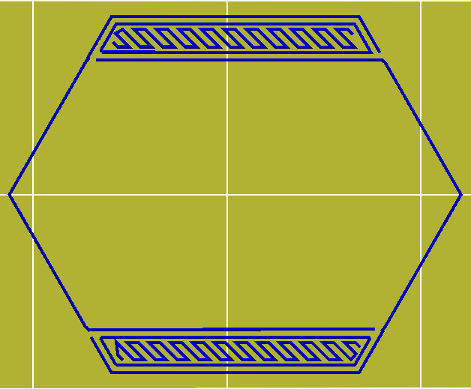
10 years ago The test stl can be found here http://sproutform.com/physibles/43
I printed an object with a single wall that is thinner than the extrusion width. Version 0.9.8 is vastly improved, as you will see in the photos. However, both versions failed to connect the thin wall to the rest of the print.
in the photo with the arrows, the double red arrow shows how the perimeter pulls inward at the ends. It just seems like it didn't make that line long enough.
The yellow arrow shows the perimeter start/stop. Though this is mostly a different issue, I added that in there because I'm wondering why Slic3r chose to start/stop the perimeter there instead of where the thin perimeter joins the rest of the model. Also, it only did this on one side. On the backside, it start/stopped the perimeters where i'd expected it to. Overall though, that start/stop looks excellent. The photo really exaggerates it's visibility. Nice job on that.
Config file: http://paste.kde.org/651014