 Tdemuren15
commented
4 years ago
Tdemuren15
commented
4 years ago Current status can be found in wiki: https://github.com/spacecraft-design-lab-2019/documentation/wiki/Mechanical-Testing
Open maholli opened 4 years ago
Tdemuren15
commented
4 years ago Current status can be found in wiki: https://github.com/spacecraft-design-lab-2019/documentation/wiki/Mechanical-Testing
How it works
The burn wire circuit works by "short circuiting" the battery across a small piece of nichrome wire. Because the wire has low resistance, lots of current flows from the battery through the wire which heats the wire up very quickly.
To implement the scheme described above, we need an electrical switch that lets us briefly "short" the battery across this piece of nichrome wire. That circuit is shown below. Practically, our switch (and battery) can't handle a complete short, so we throttle the amount of current allowed through the switch by pulsing the signal on "BURN1."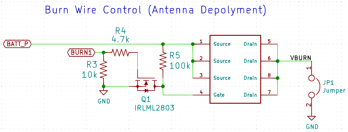
The code to do this is quite simple:
We perform the pulsing (known as pulse-width modulation: PWM) on the
board.BURN1pin and then deinitalize the pin to prevent inadvertently using the pin again in the future.Using the code
To use the above code, save it on the pycubedmini board in a file title
burn.py. Plug the mainboard into a Z panel board USING THE CABLE LABELED +Y (since our flat flex was designed when we had burn wires on the +/- Y panels). Next, make sure you have a battery connected to the mainboard. The simplest way to do this is using the VBATT and GND connector on the mainboard. Plug the mainboard into your computer and open Mu. Inside Mu, open the serial terminal (REPL) and typeimport burnand press enter. Now you're ready to test! Now you can enter something like:burn.burn(FREQUENCY=1000,DUTY_CYCLE=22000,DURATION=3)and as soon as you press enter, the burn wire will be active. The terminal will print something like this:Note the code will turn the neopixel red while the wire is active.
In the REPL, you can re-enter
burn.burn()and proceed to tune the performance of the burn wire. I recommend you keepFREQUENCYat 1 kHz, and try and keepDURATIONas short as possible (<5 sec).IMPORTANT
You need to carefully increase the value for
DUTY_CYCLEto avoid damaging the circuit, batteries, or the board. This value is a 16bit integer with 0xFFFF (2^16) representing 100% on and 0x7FFF (2^15) representing 50% on (isn't hex cool?). Note in the code you can see how duty cycle is calculated:(DUTY_CYCLE/0xFFFF)*100Keep in mind, the wire will get 🔥 HOT 🔥. Over time, as the wire gets heated over and over again, it is possible for it to break. Unsolder the wire and attach a new one. Try and make it look as close as the original: short, solder all around the wire. You can't actually solder to the Nichrome wire, so you're basically just holding it there with solder and trying to make the best electrical contact you can.