spacetelescope / webbpsf

James Webb Space Telescope PSF simulation tool
https://webbpsf.readthedocs.io
BSD 3-Clause "New" or "Revised" License
116 stars 62 forks source link

MIRI PSF jitter_sigma #674

Open amn3142 opened 1 year ago

amn3142 commented 1 year ago

Based on fitting to point sources and allowing the webbpsf parameters to vary, it appears that the MIRI PSF jitter_sigma parameter is about a factor of 10 higher than the default value in webbpsf. I am reaching out to see if others have also noted this, or it is a unique characteristic of whenever I was observing.

Also I was wondering if others have noted other parameters that should also be adjusted to fit the observed point spread function well?

obi-wan76 commented 1 year ago

Hi @amn3142, Thanks for your comments. Yes, we have seen the same effects on MIRI but also across the other detectors. This is not really jitter but instrumental effects, e.g., charge distribution within the different instruments. Currently, instrumental effects are not included in webbpsf. We are working on a couple of solutions to implements some proxy for charge diffusion, see PR 671, and also IPC effects, see issue 670.

Here is some relevant reference for this effect observed in MIRI, in particular, the Brighter-Fatter Effect (BFE) https://ui.adsabs.harvard.edu/abs/2023arXiv230313517A/abstract

amn3142 commented 1 year ago

Thank you so much for this info!! It is interesting how strong this effect is, e.g. I see it in F560W even though my sources are well below the saturation limit, with max total DN over the whole ramp of ~11,000. In F2550W the max DN is ~ 45,000 so closer to the saturation limit, but we require a similar 'jitter_sigma' to fit the PSF in both filters.

mperrin commented 1 year ago

Can you let us know which dataset(s) you're looking at? I can check the guiding information to verify that indeed the actual guiding jitter was around its typical 1 mas value in those datasets.

And yes, completely agreed it's quite interesting how strong this effect is. There may be other aspects not yet fully understood too ("unknown unknowns")... It's definitely an open area to better understand how to sync up models and data.

Another factor you should be aware of is that the models for field dependence within MIRI are relatively uncertain. The ground testing data for MIRI did not include very thorough coverage over the full FOV. See this plot, from https://webbpsf.readthedocs.io/en/latest/jwst.html#id5 : 
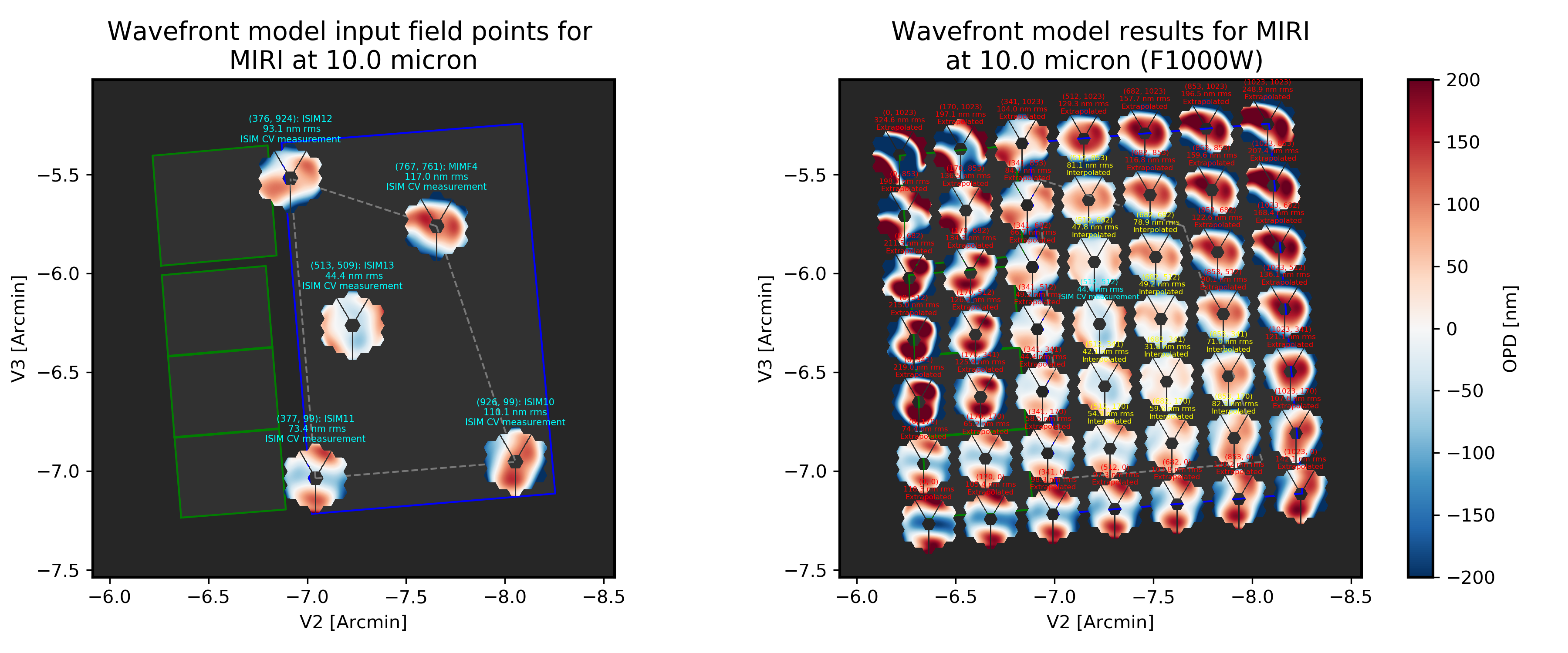
Particularly in the upper right corner (and the upper left "bonus field" through the Lyot coronagraph area) there was no ground testing WFE, and the model extrapolates, and probably not too accurately. The models for this have not yet been improved to use flight sensing data. This may not be a relevant effect for your data, but I wanted to at least mention it.

amn3142 commented 1 year ago

Thanks! My target is right in the center of the main FOV, so hopefully the field dependent effects aren't as important. But at one point we were trying to use a star near the edge of the FOV to model the PSF so that may explain partly why it didn't work. This is for proposal ID 2046 target name DESJ0405-3308-COPY

mperrin commented 1 year ago

Hi @amn3142. I just spot checked the guiding telemetry for one of your exposures (the first dither pos in F560W, I believe), and all looks nominal on the guiding. Measured jitter inferred from FGS+ACS telemetry is 0.9 mas; completely typical. FYI see attached plots.

This is an example of the engineering evidence showing that, whatever is causing the observed additional small blurring of PSFs, it's not any measurable increased jitter in the line of sight guiding.

Plot 1: Time series plot of guiding telemetry before, during, and after this particular exposure. You can see the guiding settle down at the start, followed by three big obvious impulses and oscillation ring downs (this is the MIRI filter wheel advancing three steps to put F560W into the beam!), and then the guiding stabilizes again before the actual exposure happens:

Unknown-4

Plot 3: And here's a 2D scatter plot and histogram of the same data, showing the guider centroid offsets during the exposure. Same data as in the center plot above during the green highlighted section, displayed in XY space instead of as a time series.

Unknown-3

amn3142 commented 1 year ago

Wow! thank you SO much for looking at this!!! Yes we are getting best fit jitter_sigma of 0.07, which seems to produce quite a good fit to the PSF for whatever it's worth.

Very cool to see how the filter wheel moving affects the space craft!!

mperrin commented 1 year ago

jitter_sigma of 0.07, which seems to produce quite a good fit to the PSF for whatever it's worth.

Exactly! But this is definitely one of our current puzzles. The jitter_sigma parameter is in arcsec per axis, so that's like 70 mas, which is inconsistent by nearly 2 orders of magnitude versus the measured jitter...

Hence our inference that this has to be some other physical effect that is also able to be modeled as a Gaussian convolution... If tweaking the jitter parameter works to yield a nice model, then great, work with it. But it's just something to keep in mind the actual physics is apparently something else other than LOS jitter.

mperrin commented 1 year ago

@amn3142 I wanted to ask, you mentioned the jitter_sigma of 0.07. Was that just best fit for one filter, or does that value seem to work well for many or all filters?

amn3142 commented 1 year ago

@mperrin I'll email you!

mperrin commented 1 year ago

Thanks - this will be helpful in making the defaults better for all users in the future

mperrin commented 1 year ago

Addressed (and hopefully resolved...) by #671, which added an implementation of a model for MIRI detector interpixel capacitance, which has turned out to be the dominant driver of the observed blurring effect. And related PR #693 which adjusts some model free parameters to better fit measured empirical effective PSFs.

amn3142 commented 1 year ago

Awesome!!!

amn3142 commented 1 year ago

Does the model incorporate flux dependent effects?

obi-wan76 commented 1 year ago

@amn3142 the pixel correlation in MIRI is represented by the convolution of a single 3x3 kernel. The charge diffusion term is an ad hoc Gaussian convolution, with no flux dependance. The overall approach seems to fit observations fairly well. A pre-release version (1.2.0) is available via webbpsf develop and the new set of data files are available here: webbpsf-data-1.2.0.tar.gz

amn3142 commented 1 year ago

I'm sorry for the ignorant github question, but I want to confirm that if I install the current develop branch this will be correct. (I am not seeing a version number for the develop branch itself, but maybe this is how develop branches work... again apologies but I don't want to mess around with the incorrect code version).

obi-wan76 commented 1 year ago

Yes, if you install from develop you should have access to the latest detector effects which are included by default. We are in the process of releasing the stable version with all the supporting documentation. In the meantime, if you have any questions about usage in regards to detector effects, please, feel free to ask your question in this issue.

Note that detector effects are now included by default in the 'DET_DIST' extension only.

If you want to deactivate IPC effects:

miri = webbpsf.MIRI()
miri.options['add_ipc'] =  False # default is True

If you want to change the default value for charge diffusion:

miri = webbpsf.MIRI()
miri.options['charge_diffusion_sigma'] = <your value>

In addition to this information you can check the PRs for detector effects that have sample code, examples, etc.

Thanks!

amn3142 commented 1 year ago

Would there be a way to include the charge diffusion effects in the 'OVERDIST' extension as well? I use the super-sampled PSF for my simulations.

amn3142 commented 1 year ago

@obi-wan76 I wanted to follow up on this, whether the detector artifacts might also be included in the over-sampled psf model as well?

mperrin commented 1 year ago

@amn3142 It turns out there is sort of a way already to get the IPC effects included in the oversampled image already; there's a special code path for doing so via the psf_grid function. See https://webbpsf.readthedocs.io/en/latest/psf_grids.html for info on that function if you've not used it already. The output data structure is different than the regular calc_psf output (since it's a grid of oversampled PSFs at N points across the detector, returned as a photutils.GriddedPSFModel instance). But the information content at each grid point has what you want.

@obi-wan76 we should think about adding a switch to enable toggling the detector effects in the oversampled extension from the regular calc_psf calls too. Would be pretty straightforward now since that code path exists for the gridded case.

obi-wan76 commented 1 year ago

As Marshall mentioned, a way to calculate an oversampled PSF with all the detector effects is via the psf_grid. For example, here is a simple code that setup a simulation based on an observation (i2d/cal/rate.fits) and calculate a single PSF at a particular location in the detector but using the psf_grid.

psf_location_list = (328,1279)
inst = webbpsf.setup_sim_to_match_file(<your observation file rate/cal/i2d.fits>)
c = webbpsf.gridded_library.CreatePSFLibrary(inst,inst.filter, detectors = inst.detector,  num_psfs = 1, psf_location = psf_location, fov_pixels = 50 )
grid = c.create_grid()

grid is a GriddedPSFModel When in doubt, you can always check the header of the gridded fits file (by default it will save the file in your working directory). The header should show the detector effects in the following way:

CHDFTYPE= 'gaussian'           / Type of detector charge diffusion model        
CHDFSIGM=                0.018 / [arcsec] Gaussian sigma for charge diff model  
IPCINST = 'NIRCam  '           / Interpixel capacitance (IPC)                   
IPCTYPA = '485     '           / NRC SCA num used for IPC and PPC model         
IPCFILE = 'KERNEL_IPC_CUBE.fits' / IPC model source file   
amn3142 commented 1 year ago

Thanks very much, I will give this a try.

On Aug 28, 2023, at 1:18 PM, Marcio Melendez @.***> wrote:

As Marshall mentioned, a way to calculate an oversampled PSF with all the detector effects is via the psf_grid. For example, here is a simple code that setup a simulation based on an observation (i2d/cal/rate.fits) and calculate a single PSF at a particular location in the detector but using the psf_grid.

psf_location_list = (328,1279) inst = webbpsf.setup_sim_to_match_file(<your observation file rate/cal/i2d.fits>) c = webbpsf.gridded_library.CreatePSFLibrary(inst,inst.filter, detectors = inst.detector, num_psfs = 1, psf_location = psf_location, fov_pixels = 50 ) grid = c.create_grid()

grid is a GriddedPSFModel When in doubt, you can always check the header of the gridded fits file (by default it will save the file in your working directory). The header should show the detector effects in the following way:

CHDFTYPE= 'gaussian' / Type of detector charge diffusion model CHDFSIGM= 0.018 / [arcsec] Gaussian sigma for charge diff model IPCINST = 'NIRCam ' / Interpixel capacitance (IPC) IPCTYPA = '485 ' / NRC SCA num used for IPC and PPC model IPCFILE = 'KERNEL_IPC_CUBE.fits' / IPC model source file

— Reply to this email directly, view it on GitHubhttps://github.com/spacetelescope/webbpsf/issues/674#issuecomment-1696354444, or unsubscribehttps://github.com/notifications/unsubscribe-auth/AEA6XOTTEF4S7R4AMRIV3GDXXT4JDANCNFSM6AAAAAAYQXEGJE. You are receiving this because you were mentioned.Message ID: @.***>


Anna M. Nierenberg

Assistant Professor Department of Physics, UC Merced annanierenberg.com