 chunkysteveo
commented
6 years ago
chunkysteveo
commented
6 years ago Just received my new (WHITE PCB) version and can echo the same here - Works fine on USB, appears to charge when an LIR2450 is in place (blue LED) and USB plugged in. Can switch on with an LIR2450 and USB connected, and interestingly when I disconnect the USB while still on it still works. Switch off and back on with just the LIR2450 and no power.. Have not looked into testing where power getting to, and also just testing another LIR2450, but this is odd behaviour indeed! It's like the USB connection trips it on, and without that initial USB trigger, it doesn't power up?
@codepope - if your board is working with both USB and LIR connected, disconnect the USB and does it still work on the battery? And then when you switch off and on, does it then fail to boot up?
Would be worth people advising which boards they have, I.E. I now have a blue PCB version with programming headers, and now a super cool white PCB with a serial-USB programming chip on the USB (very cool additon!)
 codepope
 Flet
Flet sqfmi
sqfmi chadvavra
 bmv437
 Korenchkin
 ibuildrockets
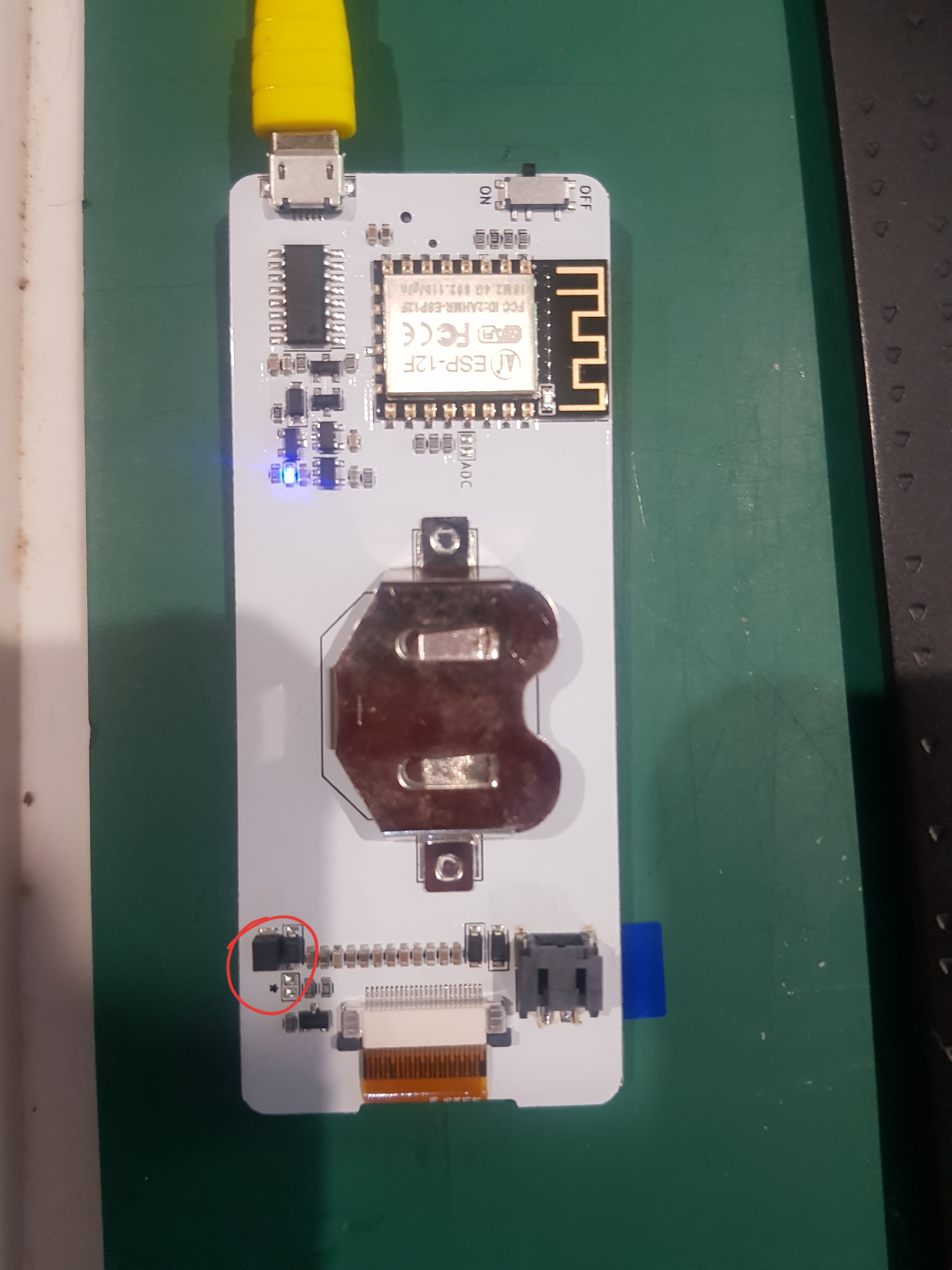
 g2rHP7prvJqO
 pastorhudson


 JonPrevost
Set up badgy on USB power, things behave as expected. Board LED glows flickers blue. Board boots up.
Popped a LIR2450 in with no USB connection and... nothing. Won't wake up, won't reset for new sketches, no LEDs glowing.
Pop in USB with LIR2450 in place, board LED glows bright blue (charging?) and board functions.
Any suggestions as to trouble shooting this?