Closed Damnned closed 3 years ago
Hello,
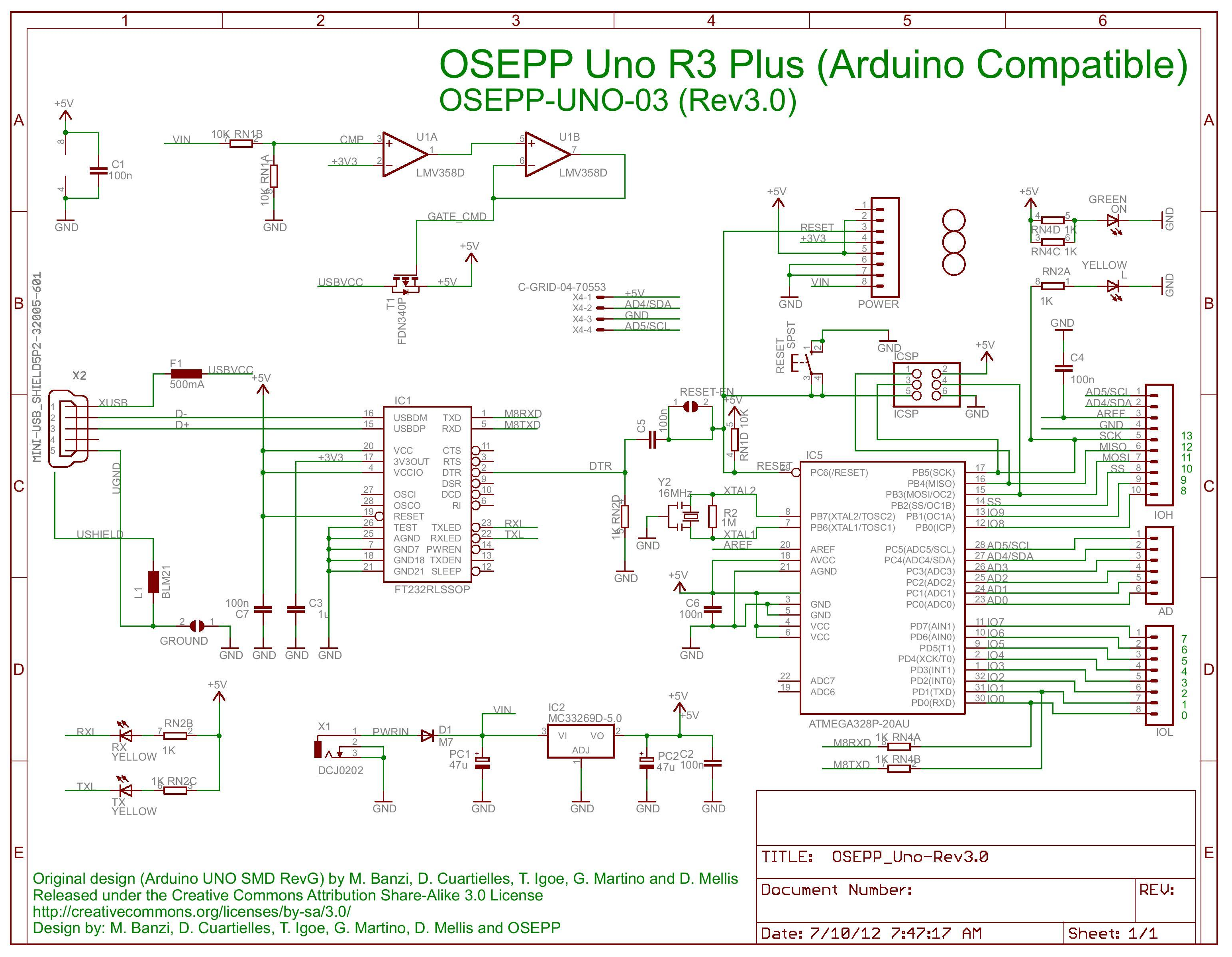
the MKS DLC V2.0 board uses same CPU as the Arduino Uno - CPU: ATMEGA328P-AU, 8bit 20MHZ.
It is not possible to use other pin than Pin 11 https://github.com/gnea/grbl/wiki/Connecting-Grbl because PWM uses hardware counter. Schematic: https://electronoobs.com/images/Arduino/tut_31/arduino_uno_scheamtic.png
Pin 11 = Β΅C PB3 -> perhaps you can figure out where this pin is available on your board (can't find schematic for MKS DLC V2.0)
Ok will send the schematic for the MKS DLC V2.0 Here is the Link https://github.com/makerbase-mks/MKS-DLC/blob/master/hardware/MKS%20DLC%20V2.0_001/MKS%20DLC%20V2.0_001%20PIN.pdf
As you can see for the Servo Motors they use Analog Pin 5 [A5] And Pin 11 for the Laser
Except your 1st image, on all other documentation it is labeled with "Probe". If you want to use grbl with RC-Servo with Atemega 328 you have to use pin 11 because of the special counter register. You may put laser on/off to analog pin 5 - this is perhaps possible via cpu_map.h https://github.com/gnea/grbl/blob/master/grbl/cpu_map.h you need to look for "spindle".
Well i am a very noob person when comes to arduino. I don't know coding. Can you edit the cpu_map for analog pin 5 to control laser. So that if a send m3 Sxx commands it will control the laser output via analog pin 5 As for my case the SG90 Servo motor.
I will upload the edited firmware and test than report you back.
BTW We can use digital pin 12 as well it is for Z Limit Switch. it is a 3 pin input too so we can connect SG90 Servo to it. As for if we can't use analog pins we can than use digital pin 12 D12.
It is right above the Probe and Extra pins on the board.
So that if a send m3 Sxx commands it will control the laser output via analog pin 5
This command will also control the servo: https://github.com/cprezzi/grbl-servo It is not possible to have RC-Servo-PWM and laser-PWM together....
You may use A3 coolant enable, controlled via M7, M8, M9 Coolant Control. In GRBL-Plotter you can define your own commands for pen-up/down (spindle/laser on/off), there you use M7 and M9.
Ok So i can only have this setup
Spindle with Z axis Control+Servo or Laser I can live with that. π
So what i get is i will upload the firmware from cprezzi/grbl-servo than i will connect the SG90 to D12 pin (digital pin 12 for Z-Limitswitch) Than it can work with m3 commands right?
Ok So just help me with changind D11 pin to D12 than it can be good to go. D11 pin is standart laser pin D12 pin is standart for Z-limitswitch. If i can direct m3 commands to D12 than the servo must work. As for i connect a laser to D12 pins than it can work too
It will not work... Please read: https://github.com/gnea/grbl/wiki/Connecting-Grbl Pin 11 has hardware PWM, which must be used to control brightness / energy of the laser. Here https://github.com/cprezzi/grbl-servo this PWM was adapted to be able to control a servo instead of a laser (pulse-width 1ms to 2ms ). 1) If you use servo, you cannot control laser-energy 2) Commands for laser and servo are same = occupied by the servo. If you send M5 (laser-off) servo moves to 0-position, if you send M3 S200 to move the servo, also the laser wil be switched on. 3) If you use a servo, you may use M7 / M9 to control coolant (which is then connected to your laser). To do so you need to gernerate GCode Laser on/off = M7/M9 - this can be done by GRBL-Plotter
Ok so what i have read i understand that if i use grbl 0.8 i can use D12 to control spindle there for laser But if i choose to use newest grbl i must use D11 for laser.
If i connect SG90 servo instead of laser servo works too. Am i on the right path?
It says you can change D12 and D11 pins for older card compatibility. So what i understand is for grbl 0.9+ to 1.1 if i disable laser mode and switch the pins D11 and D12 and connect the 3 cables of Sg90 servo to D12 pins i should work like that.
Ok so what i have read i understand that if i use grbl 0.8 i can use D12 to control spindle there for laser
Yes, but only on/off
But if i choose to use newest grbl i must use D11 for laser.
Only if you want to control the energy via PWM
If i connect SG90 servo instead of laser servo works too
Yes, if you use vers. 1.1 with laser PWM enabled and PWM frequency adapted for servo use ( https://github.com/cprezzi/grbl-servo )
It says you can change D12 and D11 pins for older card compatibility
Yes, but only laser on/off functionallity
So what i understand is for grbl 0.9+ to 1.1 if i disable laser mode and switch the pins D11 and D12 and connect the 3 cables of Sg90 servo to D12 pins i should work like that.
No, because for servo you need PWM which is only available on Pin11.
For now the only point i dont get is D11 pin has Voltage,Ground,Signal am i right? So does the D12 pin V,G,S
So i dont understand why cant i send signal to D12 pin? It has 5v,Ground and Signal output. I think it is possible. Also the D11 pin on this board is 12v for laser. Is'nt it dangerous to connect a servo to that?
D11 is a pin which can be used for input, output and special purposes, you may check datasheet: https://ww1.microchip.com/downloads/en/DeviceDoc/Atmel-7810-Automotive-Microcontrollers-ATmega328P_Datasheet.pdf Check 13.3: Alternate Port Functions - Most port pins have alternate functions in addition to being general digital I/Os The PWM used by grbl is tied to pin 11. If you try to do PWM by software, you need much more program-memory, which is not available in Atmega 328, because grbl is a huge program.
Also the D11 pin on this board is 12v for laser. Is'nt it dangerous to connect a servo to that?
You are right, but you could get the signal on J26.
Btw really thank you for your quick replies. You are awesome π
Well know i understand that it Grbl's limitation not the board or arduino uno. Basicly if i dont use grbl i can use whatever pin i want with whatever motor or laser or other things.
The only thing is that why we are paying more money to all-in-one boards if we cant use the pins π
Just buying a arduino+cnc shield for the half price is better than these all-in-one boards
Or better use grbl on an other board, just check for https://github.com/bdring/Grbl_Esp32 or https://github.com/fra589/grbl-Mega-5X or https://github.com/dungjk/grbl-stm32 or https://github.com/grblHAL/core
Just buying a arduino+cnc shield for the half price is better than these all-in-one boards
I think so too. For 12β¬ to 15β¬ you get all you need - I like to use them for my plotters... But also with pitfalls: https://grbl-plotter.de/index.php?id=quick-guide&setlang=en http://svenhb.bplaced.net/?CNC___Klappbarer_Plotter
hello it is me again i am still searching for this topic. I have found something like this can it help us for issue
"The analog input pins can be used as digital pins, referred to as A0, A1, etc. The exception is the Arduino Nano, Pro Mini, and Miniβs A6 and A7 pins, which can only be used as analog inputs."
https://www.arduino.cc/reference/en/language/functions/digital-io/digitalwrite/
To have minimum work and getting minimum trouble after grbl-changes, the problem is still:
So maybe we can work around this issue with m7 and m9 commands. Change the pin setup to A5 for spindle than use m7 and m9 commands to control the servo??
And now i am tryin another firmware it is makeblocks firmware. but still no movement from the servo :(
Man my head hurts :( i dont get anything. Btw i figured something else big trouble On the SG90 cables Brown is Ground G Red is Voltage V Yellow is Signal S
So when i directly connect the servo to this board it will never work
As I wrote: the label "servo" is only visible on one picture, probably it is a mistake - or did you buy this board with the option "servo"? Why there is no more information about that on their website? Support?
BTW: the default "coolant pin" (command M7, M9) is A3 (check https://github.com/gnea/grbl/wiki/Connecting-Grbl). On your board A3 is available on J22 https://github.com/makerbase-mks/MKS-DLC/blob/master/hardware/MKS%20DLC%20V2.0_001/MKS%20DLC%20V2.0_001%20PIN.pdf
As I wrote: the label "servo" is only visible on one picture, probably it is a mistake - or did you buy this board with the option "servo"? Why there is no more information about that on their website? Support?
Well i bought it cause i saw servo but as i gave no way of working a servo through other pins. I connected the servo to D11 and signal to ttl and it worked with xyz mode so i can have spindle and servo connected at the same time. Just will make a button switch on the cables to disconnect one of them. So i dont have to connect disconnect spindle or servo or laser every time π
Thanks for your helps and quick replies
Hello Sir; I have a All-in-one Board from Makerbase. I am Attaching the pin setup and Layout pictures too. The D11 pin is used by laser on this board. They put an empty pin for the Servos (Analog 5 - Probe ) How Can i modify GRBL To use Analog pin 5 with the Servo. So we can have both Laser and servo connected to the board. BTW most of the servo grbl firmwares disable Z-axis too I dont want to disable that too. I will use the machine as complex as possible
Image Links - The Board is MKS DLC V2.0
https://ibb.co/j4S30J4 https://ibb.co/Pjg0hQk