 swill
commented
5 years ago
swill
commented
5 years ago It is actually intentional that it is not to spec. I originally made it to spec, but there are situations where it is not ideal, so I adapted the cutout to perform better in real life. One example is with plate mounted switches. The official 2u cherry cutout is very sloppy compared to what we have, specifically for hand wired keyboards where you are not soldering into a PCB.
So in general, yes, it is not exactly to spec and that is intentional. The cutout that I use is a real world improvement to the spec which is compatible with more types of switch/plate configurations.
Let me know if you are having issues of any kind and I will help you resolve.
Thanks for taking an interest and reporting this. It is great to get feedback and engagement.
 ifohancroft
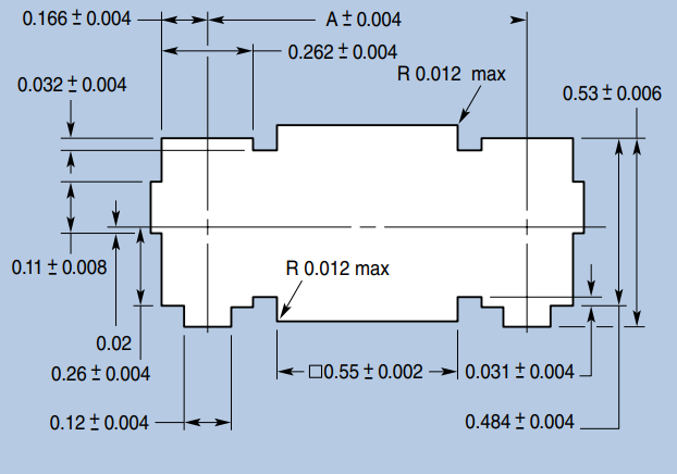


 TweetyDaBird
I don't know about the long stabilizer but the short stabilizer that gets generated when you choose Cherry Stabs Only doesn't follow/differs from Cherry's specification.
P.S. I am falling to understand the numbers of the Cherry Stabilizer draw function well, but if you wouldn't mind explaining them, I can clone the repo, fix the issue and create a pull request or I can send you all the dimensions in millimeters of a stabilizer matching perfectly the spec, so you won't have to decipher it (although, maybe it's just me finding it tedious to decipher their size specs)