 syssi
commented
2 years ago
syssi
commented
2 years ago Could you open the case and provide a photo of the PCB? Do you own a multimeter to do some measurements to identify the GPIOs? I would provide some instructions how to do it.
Closed pawelkw closed 1 year ago
syssi
commented
2 years ago Could you open the case and provide a photo of the PCB? Do you own a multimeter to do some measurements to identify the GPIOs? I would provide some instructions how to do it.
 pawelkw
commented
2 years ago
pawelkw
commented
2 years ago Yep, I do have a multimeter. Let me know what you need. I'm happy to work together to make things work.
syssi
commented
2 years ago The first step is to open the case and make sure the device is ESP32/ESP8266 based. As next step use the continuity tester of the multimeter to measure the continuity between test pads (and/or pin headers) and the GPIOs of the ESP. In best case RXD, TXD, VCC and GND are available at a pin header and GPIO0 is accessible as a test pad. If not: You have to wire some cables directly to the ESP because we want to dump the stock firmware into a file to be safe.
pawelkw
commented
2 years ago The first step is to open the case and make sure the device is ESP32/ESP8266 based. As next step use the continuity tester of the multimeter to measure the continuity between test pads (and/or pin headers) and the GPIOs of the ESP. In best case RXD, TXD, VCC and GND are available at a pin header and GPIO0 is accessible as a test pad. If not: You have to wire some cables directly to the ESP because we want to dump the stock firmware into a file to be safe.
Thanks! That thing is not that easy to open 😬 . Will get back to you when I have more time to play around with it.
syssi
commented
2 years ago Please make sure there a no screws under the white rubber pads.
pawelkw
commented
2 years ago 

No screws :( Ugh... plastics seem fused together. Heat gun doesn't do much - there seems to be no glue. Any ideas how to make it less painful?
pawelkw
commented
2 years ago Btw I found this: https://fccid.io/2ABEU-YLDD04YL/Internal-Photos/Internal-Photos-3895719
syssi
commented
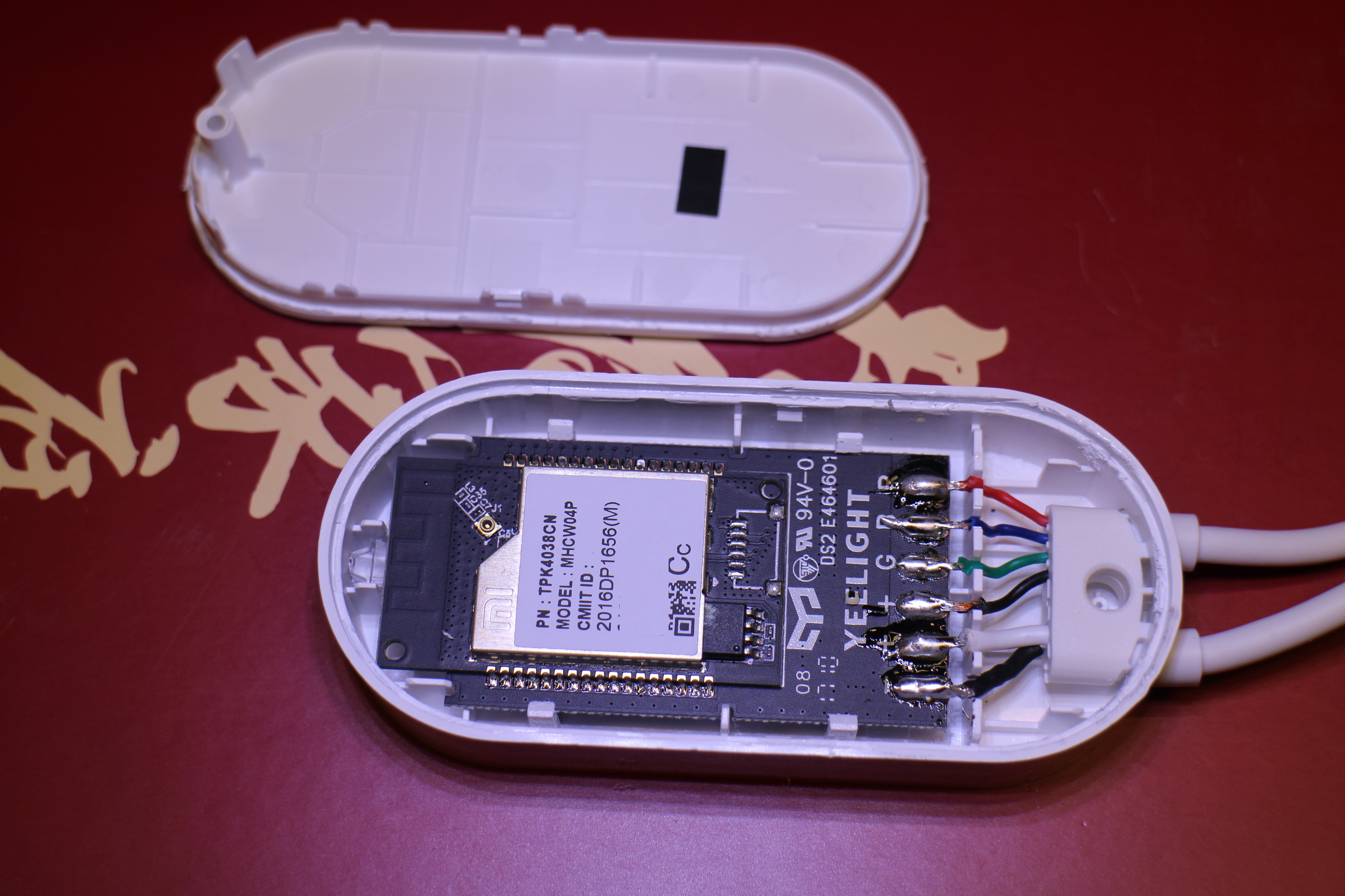
2 years ago This PCB looks very similar to the FCC photos: https://dontvacuum.me/teardowns/yeelink.light.strip1/
Sadly the microcontroller doesn't look like an ESP32. I assume it's a mediatek: https://cdn-0.fccid.io/png.php?id=3895719&page=2
We are stuck here. :-( Sorry for the mess.
pawelkw
commented
2 years ago No worries. At least we now know strip1 and strip2 won't ever be supported by your project.
On a scale of 1 to 10 how hard would it be to replace the internals with my own ESP8266 microcontroller?
I'm having major connectivity issues with the current state of this light strip so I'm tempted to try... Might be able to learn a lot too, sounds like a good project.
syssi
commented
2 years ago The hard part is to unsolder the MHCW04P module: https://dontvacuum.me/teardowns/yeelink.light.strip1/IMG_0419.JPG
If you don't want to give up you could take this road:
MHCW04P. MHCW04P because we would like to know the pinout and the purpose of every GPIO. If there is no datasheet we have to use our multimeter.MHCW04P. Set the brightness to 1% and measure all voltages. Set the brightness to 100% and measure again. You should find a pin (or a pin per color) which changes the voltage depending on the intensity controlled by the App. As soon we know the 3 PWM GPIOs to drive the different colors we can remove the MHCW04P. Instead of using white light (all colors) you should pick one color (red, green, blue) per attempt.MHCW04P.MHCW04P has it's own voltage regulator at the bottom of the (removed) module. We must make sure to power the ESP properly. Try to replicate this configuration: https://github.com/syssi/esphome-yeelight-ceiling-light/blob/main/yeelight_light_strip6.yaml
In other words: Attach the RED-PWM to GPIO13, GREEN_PWM to GPIO13 and BLUE_PWM to GPIO15. Connect GND to the mainboard (in best case the pad of the MHCW04P). Thats all!pawelkw
commented
2 years ago I got in and it's exactly what we've seen in the other pictures.
Regarding your step by step guide it means I'm supposed to desolder the WiFi microcontroller from the "motherboard"? I thought it would be easier to hook directly into the LED and power wires? 
syssi
commented
2 years ago You cannot drive the LEDs directly AFAIK. There is a LED driver circuit (mosfet per channel?) somewhere on the back of the mainboard. If you replace the driver with another solution you could replace the complete interior.
pawelkw
commented
2 years ago I see... Here's the back btw:

pawelkw
commented
2 years ago Can we make any use of the debug points you see in the top right? I have a serial to USB adapter. Could we get something useful out of that?
syssi
commented
2 years ago If you attach the adapter you can see some log messages of the stock firmware.
syssi
commented
2 years ago If you don't want to unsolder the WiFi module you could try to connect the RST pad to GND. In this case the WiFi module shouldn't start anymore. I hope the R, G, B pads are connected to the GPIOs of the WiFi module. Please measure the continuity between the test pads an the WiFi module pads. If they are connected to the WiFi module you can use these pads for your measurements and you could solder the GPIOs of the ESP to these pins.
pawelkw
commented
2 years ago 
Found the pins. At this point I gotta order an ESP. Any ones you could think of that would fit in this case?
syssi
commented
2 years ago If you don't need a BLE gateway you could use an ESP8266 (f.e. a WeMos D1 Mini).
pawelkw
commented
2 years ago I managed to get it working with a Pi Pico to control the strip:

But now the ESP module came in:

So I want to unsolder the mediated chip and put this one in. Could you guide me to some resources of what to do exactly with that yaml file and how to get ESPHome onto that chip?
Also how do I know how the GPIO13 etc map onto the D0 - D7 pinout on my board?
syssi
commented
2 years ago esphome run yeelight_light_strip6.yaml to your ESP (via USB cable)D7): REDD5): GREEND1): BLUEAttach VCC and GND and give it a try!
syssi
commented
2 years ago Also how do I know how the GPIO13 etc map onto the D0 - D7 pinout on my board?
Please google "wemos d1 mini pinout". You should find something like this:

syssi
commented
2 years ago How to install ESPHome on a linux host and flash the first YAML configuration:

Please ignore the git clone of the seplos project. Just make sure the yeelight_light_strip6.yaml is part of your working directory.
pawelkw
commented
2 years ago Wow, thanks.
Just one last thing before I proceed:
in the yaml:
esp32:
  board: esp32doit-devkit-v1
  framework:
    type: esp-idf
    sdkconfig_options:
      CONFIG_FREERTOS_UNICORE: y
    advanced:
      ignore_efuse_mac_crc: true
Probably doesn't make sense considering I'm flashing it on a completely different board?
I've found this: https://docs.platformio.org/en/latest/boards/espressif8266/d1_mini.html but not sure if and how I would edit the yaml to make things compatible.
syssi
commented
2 years ago Jap please swap this section to the WeMos board (dual core ESP32).
pawelkw
commented
2 years ago Jap please swap this section to the WeMos board (dual core ESP32).
Yeah, not that easy apparently:
INFO Reading configuration yeelight_light_strip2.txt...
Failed config

output.ledc: [source yeelight_light_strip2.txt:19]

  Component output.ledc requires component esp32.
  platform: ledc
  pin: GPIO13
  id: output_red
output.ledc: [source yeelight_light_strip2.txt:22]

  Component output.ledc requires component esp32.
  platform: ledc
  pin: GPIO14
  id: output_green
output.ledc: [source yeelight_light_strip2.txt:25]

  Component output.ledc requires component esp32.
  platform: ledc
  pin: GPIO5
  id: output_blue
Config:
substitutions:
  name: yeelight-light-strip2

esphome:
  name: ${name}

esp8266:
  board: d1_mini

wifi:
  ssid: !secret wifi_ssid
  password: !secret wifi_password

ota:
api:
logger:

output:
  - platform: ledc
    pin: GPIO13
    id: output_red
  - platform: ledc
    pin: GPIO14
    id: output_green
  - platform: ledc
    pin: GPIO5
    id: output_blue

light:
  - platform: rgb
    name: "${name} rgb"
    red: output_red
    green: output_green
    blue: output_blue
gamma_correct: 0Oh, sorry. I missed a detail. The PWM component of the ESP8266 isn't called ledc. Please google esphome pwm esp8266 and use the suggested platform.
syssi
commented
2 years ago Please try:
substitutions:
  name: yeelight-light-strip2

esphome:
  name: ${name}

esp8266:
  board: d1_mini

wifi:
  ssid: !secret wifi_ssid
  password: !secret wifi_password

ota:
api:
logger:

output:
  - platform: esp8266_pwm
    pin: GPIO13
    id: output_red
  - platform: esp8266_pwm
    pin: GPIO14
    id: output_green
  - platform: esp8266_pwm
    pin: GPIO5
    id: output_blue

light:
  - platform: rgb
    name: "${name} rgb"
    red: output_red
    green: output_green
    blue: output_blue
gamma_correct: 0Feel free to ask more questions if it still doesn't work.
pawelkw
commented
2 years ago I'm a bit stuck for now, my soldering iron can't handle the small chip lanes, so I cannot proceed. I did get the ESP to work and connect to home assistant though, so that's a good thing. I'll order a smaller soldering tip soon so I can go further but it seems it's gonna work.
Would it be possibly to add support for this variant of the Lightstrip? Perhaps it's just a swap-in replacement with the strip6? I can provide photos, etc as needed as I own the device. I also have the strip6 if that helps to find differences.