teemuatlut / TMCStepper

MIT License
512 stars 201 forks source link

ATSAMD51 TMCStepper (TMC2130) Compatability #185

Closed dev-000 closed 3 years ago

dev-000 commented 3 years ago

@teemuatlut I was trying out the TMCStepper library with an Adafruit Feather M4 Express board. I am currently running into issues. Would you know if this library was ever tested with an ATSAMD51 M4 series chips?

My hardware setup is an Adafruit Feather M4 Express and a Trinamic SilentStepStick -TMC2130 board.

Connections are as follows

I had wired up the motors correctly and tried run a basic full rotation code but it didn't work. So what I tried then was to check if the SPI connection and if I was able to read IOIN register with the following code[Ref].

#include <TMCStepper.h>

#define DIR_PIN   22   // Direction  // 20 for M0(ATSAMD21), 22 for M4(ATSAMD51)
#define STEP_PIN  21   // Step        
#define EN_PIN    19   // Enable      
#define CS_PIN    18   // Chip select 

#define R_SENSE   0.11f // For SilentStepStick 

TMC2130Stepper driver(CS_PIN, R_SENSE);  // Hardware SPI

void setup()
{
  delay(2000);
  pinMode(EN_PIN, OUTPUT);
  pinMode(STEP_PIN, OUTPUT);
  pinMode(DIR_PIN, OUTPUT);

  digitalWrite(EN_PIN, LOW); // Enable Driver
  digitalWrite(STEP_PIN, LOW);
  digitalWrite(DIR_PIN, LOW);

  Serial.begin(9600);
  while (!Serial);

  SPI.begin();
  driver.begin();

  driver.rms_current(1000);        // Set motor RMS current
  Serial.print("vsense = ");
  Serial.print(driver.vsense());
  Serial.print("\trms_current = ");
  Serial.print(driver.rms_current());
  Serial.print("\tirun = ");
  Serial.print(driver.irun());
  Serial.print("\tIOIN = ");
  Serial.println(driver.IOIN(), HEX);

  driver.rms_current(600);        // Set motor RMS current
  Serial.print("vsense = ");
  Serial.print(driver.vsense());
  Serial.print("\trms_current = ");
  Serial.print(driver.rms_current());
  Serial.print("\tirun = ");
  Serial.print(driver.irun());
  Serial.print("\tIOIN = ");
  Serial.println(driver.IOIN(), HEX);

  digitalWrite(EN_PIN, HIGH); // Disable Driver

}

void loop()
{
}

With the M4 board, I am getting the following result

vsense = 0 rms_current = 994 irun = 17 IOIN = 11000069 vsense = 0 rms_current = 1049 irun = 18 IOIN = 11000069

which seems to suggest that the drive current is not getting set properly.

When I replace the M4 board with an M0 Feather Basic board(Direct drop in replacement on a breadboard without changing any hardware other connection) and I upload the code with just changing the DIR pin value as it's mapped differently I get the following output

vsense = 0 rms_current = 994 irun = 17 IOIN = 11000068 vsense = 1 rms_current = 581 irun = 18 IOIN = 11000068

I am able to run a stepper without any issue with an M0 board with the TMCStepper library, which seems to suggest it might not be a hardware issue. I have double-checked the breadboard connections to ensure it's not loose or anything.

When I switch back to the M4 board and run the above code, sometimes(1 out of 10 times) I get the vsense value as being set and get the following result same as M0

vsense = 0 rms_current = 994 irun = 17 IOIN = 11000068 vsense = 1 rms_current = 581 irun = 18 IOIN = 11000068

So I am starting to suspect it might be an issue with SPI communication with the M4 board. I currently don't have a logic analyser to check if that is indeed the case. Is there any way for me figure out if its a hardware issue or a library issue? I had glanced through the datasheets of the ATSAMD21G18 and ATSAMD51J19A SPI sections and they look mostly similar. Can it have something to do with clock speed(ATSAMD51J19A runs at 120MHz)?

I have seen this thread as well where someone had issues with the library and Teensy 4.1 board because of speed. I tried changing the code as per the bug fix mentioned there but it didn't help fix my issue.

Can you please help point me in the right direction on how to debug this? If you think the library should work with the ATSAMD51 chips then I will focus my attention on potential hardware issues.

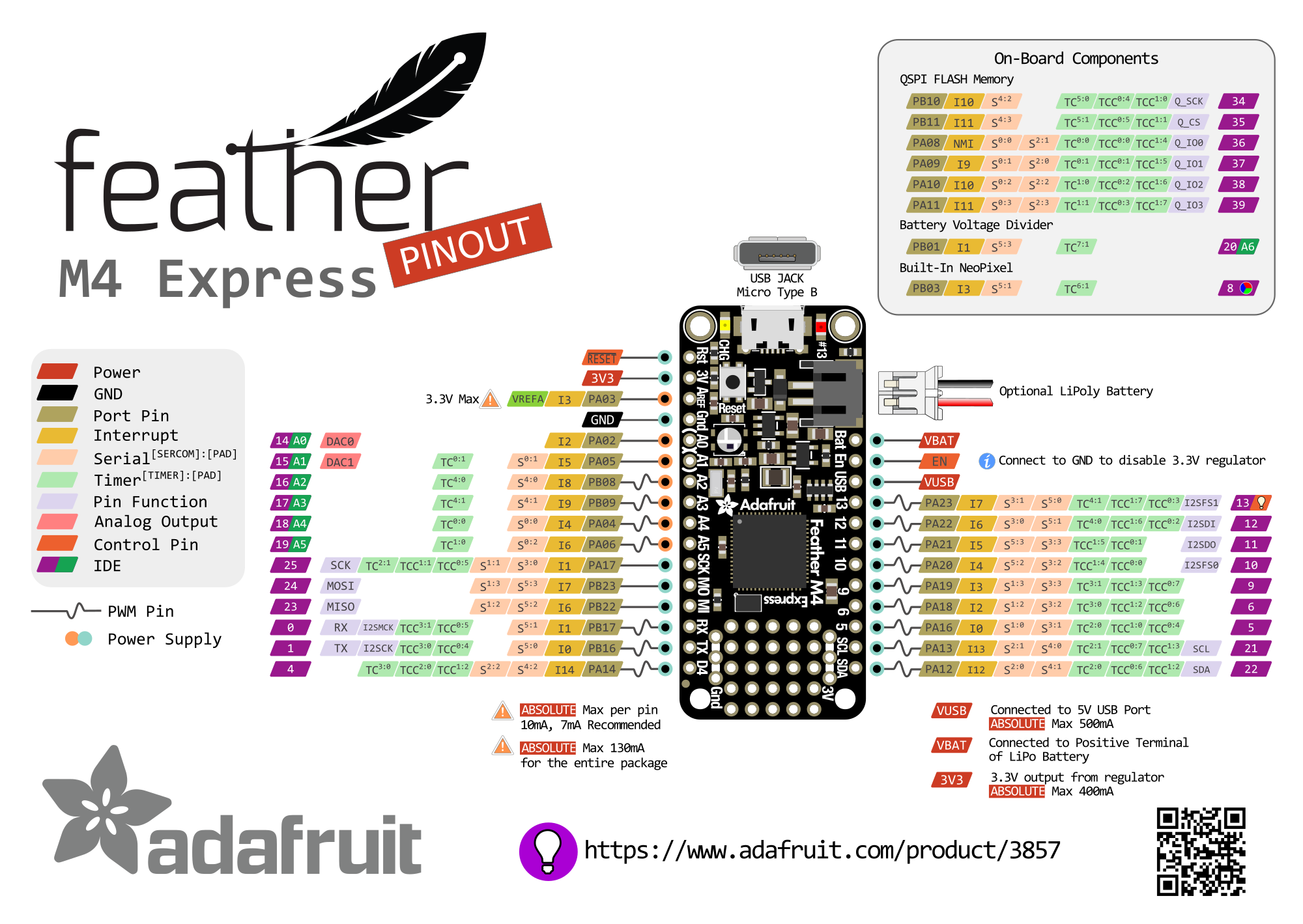
I am attaching the pinouts of the 2 Adafruit boards which I am using. Feather M0 Basic Feather M4 Express

teemuatlut commented 3 years ago

It's possible it might be an issue with board speed like with the Teensy. Try adding this to your code:

void TMC2130Stepper::switchCSpin(bool state) {
  delay(2);
  digitalWrite(_pinCS, state);
  delay(2);
}

It should override the weakly defined symbol from the library. The board is not terribly expensive so I'm considering getting one for testing but it'll take a bit to arrive.

dev-000 commented 3 years ago

Thanks @teemuatlut for the suggestion. I had already tried adding the delay for CS pin based on Teensy post. But it didn't help. I tried adding the 1ms delay as you mentioned. Not much change. It works sometimes, sometimes it doesn't. This is making me incline towards the fact that its an SPI timing issue. The two times I got the stepper motor to run with the board, it was running intermittently, missing a lot of steps, not moving properly at all. I tried adding small series resistors on SPI lines too to see if that will help but it didn't. I tried another ATSAMD51 board(Itsybitsy M4) but that shows the same issue as well.

Any help to fix this issue is highly appreciated.

Depending on where you are on the whole wide planet, I may be able to get an M4 board to you to test if needed. 🙂 You can PM me.

teemuatlut commented 3 years ago

I've ordered the same Feather board from the UK so I'll be able to test this out myself.

dev-000 commented 3 years ago

Hi @teemuatlut, Wondering if you got a chance to check out the library with your new ATSAMD51 board? Are you getting similar communication errors as I am?

teemuatlut commented 3 years ago

I've yet to receive the board I ordered so I haven't been able to test anything.

teemuatlut commented 3 years ago

I got my board a couple of days ago and I was able to test your code myself. I changed the readouts to the loop function to put more stress on the comms but I saw no issues with running the code as is. image

dev-000 commented 3 years ago

@teemuatlut Thanks a lot for taking the time to test it. Ever since you posted the result, yesterday I was uneasy as to why it worked for you and not for me. So what I did was, I completely disassembled the circuit connections and started from scratch once again. Once I made the connections back and ran the code above it started working as expected. Same as the result posted by you. So I think what was at fault was probably a signal integrity issue in the SPI communication because of my breadboard wiring, as I was getting the expected results before albeit rarely(1 in 10 or so). Connections were exactly the same as before and no changes. For the ItsyBitsy M4 board also I was using the same wiring so I am mostly certain that it was a signal integrity problem. Now ItsyBitsy M4 board also works all the time.

Here comes the fun part. Even after I got this working, I couldn't get the motor rotation code working. So what seemed to be the problem in the basic motor rotation code(That was the main reason I tried the register reading code in the first place) was that I had physically wired up DIR_PIN to SDA pin, STEP_PIN to SCL_PIN on M4. In the code initialisation, I had given the following based on Adafruit's Pinout Diagram

#define DIR_PIN   22   // Direction  // SDA Pin
#define STEP_PIN  21   // Step  // SCL Pin

This was what was causing it to not work. It seems Adafruit's team made a mistake in the Pinout image. They swapped the Digital Pin values of SDA and SCL in the image. Actually, it should be SDA --> Dpin 21, SCL --> Dpin 22 Once I found this issue, all I needed to do was swap the pins and get the motor code working. And it did work. I will ping the folks at Adafruit to fix it.

Both the above issues combined made me think that it might be an issue with the SAMD51 chip when I tried this for the first time. Murphy's Law struck big time.

After testing it, I can ascertain that the library works fine with SAMD51 chips. 😀

Thanks once again thank you for all your help. Without you replicating this issue at your end, I would probably have never found these mistakes. Keep up the awesome work with the library. 😀

teemuatlut commented 3 years ago

Can confirm. This is from the variants/feather_m4_can/variant.cpp file

const PinDescription g_APinDescription[PINS_COUNT]=
{
  ...
  // 21..22 I2C pins (SDA/SCL)
  // ----------------------
  { PORTA, 12, PIO_SERCOM, PIN_ATTR_PWM_E, No_ADC_Channel, TC2_CH0, TC2_CH0, EXTERNAL_INT_12 }, // SDA: SERCOM2/PAD[0]
  { PORTA, 13, PIO_SERCOM, PIN_ATTR_PWM_E, No_ADC_Channel, TC2_CH1, TC2_CH1, EXTERNAL_INT_13 }, // SCL: SERCOM2/PAD[1]
dev-000 commented 3 years ago

Yup. That's how I found out too. It started working when I used another pair of pins for STEP and DIR. Then was able to find the code in the variant.cpp file.