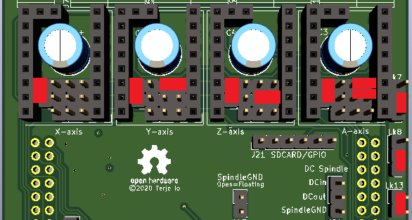
Open M10CUBE opened 3 years ago
Hi @terjeio . Grate design. First of all did you build it? Is everything working OK or there are errors on PCB. Checking PCB for errors KiCAD (nightly builds V6) reported many. (not warnings) Most of them courtyard. Then what I did was to transfer your design into M10CUBE format. I did not sent any for FAB waiting your approval first I did not change anything just connected power from 40 pin Raspberry connector to your board. So this board now can be part (partially) to M10CUBE ecosystem.
I also see that you are contributing to PICO GRBL design. Here is the link of the post containing details about that: https://github.com/grblHAL/RP2040/discussions/3#discussioncomment-1541073
One last thing. Can I put "Polulu style motor driver "dummy" PCB from project " CNC_Boosterpack" here on CNC_Breakout_Nucleo64 project to control the DM556 driver? Or signals are inverted? I can not see the KiCAD design because of missing many libraries on the Polulu style motor driver "dummy KiCAD design " Having said that I like to contribute as far as I can on NUCLEO 64 design as well. Thank a lot
Yes I have built and bench tested it. There are only courtyard errors when I run DRC, this with v5.1.2. The courtyard errors can be ignored, they are mostly from the DRC ignoring which side of the board the components are mounted.
The "dummy" driver can be used as a replacement for all boards that has Polulu style drivers. Yes, signals are inverted but that can be "corrected" by inverting them electronically in the driver configuration.
I see now that the design is in KiCad4 format, so symbols has to be remapped. Also, if made with a 2 layer board R4 should be replaced with a track on the top layer.
Thanks @terjeio. I will forget the errors. R4 can be replaced with zero resistor I think. Before converting it is nice to post the PDF of the schematic so to understand the circuit of the DUMMY since it is unreadable in KICAD6 As you see I am preparing an idea how to combine your NUCLEO64 + PICO design from phil-barrett + M10CUBE to make a new PICO GRBL PCB (monolithic or modular or both). Before start designing I need to examine carefully what is done so far, then to come up with a dissent proposal. Meanwhile I will also connect the I2C bus to my M10CUBE+NUCLEO CNC BRAKE OUT design and post it here with the KICAD files. Then I will FAB 5 boards for testing
R4 can be replaced with zero resistor I think.
It is a 0R resistor...
The dummy motor project has now been converted to v5 format.
OK @terjeio KiCAD now reads the schematic . You are using the connector CONN_PWR_2P_3.5MM_CAMBLOCK The one I find is this: https://www.aliexpress.com/item/33029158756.html?spm=a2g0o.store_pc_groupList.8148356.6.13457f61oGaiBR Problem is that can not have to side by side. Is your connector without the plastic in the sides? Otherwise I have to order the 4P version I bought for M10CUBE from this supplier many types but all was 3.81mm
You are using the connector CONN_PWR_2P_3.5MM_CAMBLOCK
Either that or 2.54mm pin headers. User choice.
Problem is that can not have to side by side. Is your connector without the plastic in the sides?
Not sure what you mean by this, the connectors I use can be slided into each other. I have 2P and 3P variants which can be joined to whatever number of pins I want. Or do you mean 2.54mm pin headers with white plastic (shroud?) around them which some steppers comes with a mating plug for?
I bought for M10CUBE from this supplier many types but all was 3.81mm
You can change the PCB to match those? Not sure if there is enough room though.
Can you please point me to the supplier for your connector to colied with others so as to form a continuous one? so i can only do 2p and 3 p like you. I do not want to change the pcb at the moment concerning the connectors. thanks
On Sat, Oct 30, 2021 at 9:23 PM Terje Io @.***> wrote:
You are using the connector CONN_PWR_2P_3.5MM_CAMBLOCK
Either that or 2.54mm pin headers. User choice.
Problem is that can not have to side by side. Is your connector without the plastic in the sides?
Not sure what you mean by this, the connectors I use can be slided into each other. I have 2P and 3P variants which can be joined to whatever number of pins I want. Or do you mean 2.54mm pin headers with white plastic (shroud?) around them which some steppers comes with a mating plug for?
I bought for M10CUBE from this supplier many types but all was 3.81mm
You can change the PCB to match those? Not sure if there is enough room though.
— You are receiving this because you authored the thread. Reply to this email directly, view it on GitHub https://github.com/terjeio/CNC_Breakout_Nucleo64/issues/3#issuecomment-955573326, or unsubscribe https://github.com/notifications/unsubscribe-auth/ADK6RSWXSXVMQS62CSUBYDTUJRA3ZANCNFSM5GYVKL3A . Triage notifications on the go with GitHub Mobile for iOS https://apps.apple.com/app/apple-store/id1477376905?ct=notification-email&mt=8&pt=524675 or Android https://play.google.com/store/apps/details?id=com.github.android&referrer=utm_campaign%3Dnotification-email%26utm_medium%3Demail%26utm_source%3Dgithub.
-- Vasilis Vorrias
Electronics and Automation
M10CUBE project: https://hackaday.io/project/171770-m10cube GitLAB : https://gitlab.com/m10cube/m10 email: @. @.> Skype: vorrias_home Phone home: +302421049323 <+30%202421%20049323>
Against GM food
I am waiting for new delivery - nearly four months now so I do not think I should link to that supplier (from china via ebay). However, I found it on Aliexpress, it is this type.
Four months! we had that problem in Greece last year but now delivering is starting normal. So I choose the discrete ones since dificult to source the ones that go side by side. But I will look for it I order from the supplier you pointed out from Aliexpress since my supplier has only packets of 50. since I have many many 2P, 3P, 4P 3.5mm plugs (left over from our motion drive installations) I paced order for the corresponding sockets in packet of 30 angled because these can be used as straight by straightening. (not the other way around). To see how it will go and I will order more variation in the future. I may switch to the 3.5mm instead of 3.81mm for our M10CUBE. Now I only want to connect I2C on the M10CUBE+CNC_Breakout_Nucleo64 and sent it for FAB. So until the connectors arrival I will have the PCBs on my LAB to give it a try
Hi @terjeio Recently Dr Dalaris from techexplorations.com found M10CUBE idea interesting and wants to make a podcast about it.
As you know KiCAD 6 announcing date is in December. I'm thinking it is a good idea when I will speak in podcast to announce as a case study the mix of the a) CNC_Breakout_Nucleo64 by @terjeio + M10CUBE b) Pi Pico CNC @Phil Barrett + M10CUBE
That will give publicity to all the topics involved specially the GRBLHAL project I will invite Phil Barrett as well from PicoCNC project to help me move the new version he is preparing into the M10CUBE format. The way I see we have the following advantages by doing that. 1 - KiCAD 6 design 2 - M10CUBE framework 3 - Nucleo64 and Raspberry Pi Pico CNC designs on board (both fits nicely into 90 X 90 mm) 4 - Ready for GRBLHAL 5 - Final design can be integrated with others M10CUBE modules like I/Os already done (V1 but I am doing V2 now)
All that without sacrificing any design done so far with Nucleo64 CNC or Raspberry Pi Pico CNC but only adding all the M10CUBE features.
Dr Dalmaris placed the podcast on December but I am thinking to move it from next year so to have time to discuss and document the idea better.
The only thing you need to jump on M10CUBE is only that:
1 - to have 90x90mm for PCB dimension (on places where I/O connectors are you can go up to 100mm) 2 - to have mounting holes for M3 screws located 4x4mm from the edges of the 90 x 90 mm PCB 3 - on one side on specific location a 40 pin Raspberry connector must be located. Even if you have it unconnected
I already have a template made (KiCA6 nightly builds) to help out the transition. https://drive.google.com/drive/folders/1f1UmG2nwTirFiiY7XVGedgxhAJYgD1Qi?usp=sharing On the coming M10CUBE podcast both designs (Nucleo64 CNC and Raspberry Pi Pico CNC) will explored as successful case studies.
So I really want to hear from you on that.
Interesting, my design is open hardware so feel free to modify it as you please. I see that you have already added the Pi header above. BTW in addition to routing I2C to that header you may want to route UARTTX/UARTRX as well? For I2C you have included the STROBE signal (from U9/pin2)?
Note I have no intention of selling it myself, and the component choices I've made is not well suited for assembly by a manufacturer such as JLPCB? Some, such as the optocouplers, has to be substituted with similar ones from the manufacturers parts list?
Hi @terjeio. I am not doing it for money as well. I have no intentions of selling Yes absolutely right. Stobe signal crossed my mind but after your remark it will be a MUST. That way we will have no delays I2C inputs can be used as good as direct on board inputs. As you can see from our I/O module used pin 19 of MCP23017SS (INPUT part) to connect in pin 13 of RasPi connector (I2C_INT name). Easy to include that as well How can we will handle it on the GRBLHAL? It must be a routine to handle the STROBE and jump to see what info is on the I/O chip. On the CPU side A STROBE multiplexer must provided if we have more strobes or to have separate pins. A solution to that it is already on the market and will soon incorporated into M10CUBE design as soon as CPUS include it. That is I3C . 10MBPS and no need for a separate interrupt pin At the moments I will incorporate the already designed 13 pin on Raspberry PI and se how it goes. UARTTX/UARTRX ? Yes nice. Never crossed my mind. I will do it Yesterday I finished (the long waited PCB in my lab) the M10CUBE Input / output module so to try it with NUCLEO64, ARDUINO or any CPU and see results. Thanks for engaging in the idea and I hope to see some next design of yours on the M10CUBE format. If we make a "bin" full of various M10CUBE designs many will benefit. Now on the drawing M10DX01-01.pdf board to see how to do it...
How can we will handle it on the GRBLHAL? It must be a routine to handle the STROBE and jump to see what info is on the I/O chip.
I guess I have to allow for a way to poll multiple devices. The keypad plugin is one that "uses" the strobe pin to read keypresses. A I2C strobe HAL function pointer entry that can be used by several plugins at the same time by "chaining".
On the CPU side A STROBE multiplexer must provided if we have more strobes or to have separate pins.
Not neccesarily - polling can be used. The strobe input is active low, this allows for wire-OR'ing several sources to it.
I guess I have to allow for a way to poll multiple devices. The keypad plugin is one that "uses" the strobe pin to read keypresses. A I2C strobe HAL function pointer entry that can be used by several plugins at the same time by "chaining".
Nice lets do it Not neccesarily - polling can be used. The strobe input is active low, this allows for wire-OR'ing several sources to it.
Mm.. If you have 5 MCP23017SS strobing and you have wire-OR'ing the strobes even if you start polling you have no idea with MCP23017SS asking you attention for you to poll. The way I see is to stick only with two independent strobes for high speed input. 1 - Port B MCP23017 is used now as input and we are using pin 13 of RASPI bus as STROBE B. That is 8 X INPUTS 2 - In case of a future module with 16 X INPUTS (using port A as INPUT) we will use pin 11 of RASPI bus as STROBE A
We must be careful not to enable strobe on other cards on the bus. I think having 16 inputs strobed is more that adequate at the moment,even for a heavy CNC project. Others I/Os from other modules will do business as usual.
As I said to all these problems are solved with I3C.
But still if you have some other idea I am listening . I may be wrong.
I might be wrong too... I think I'll add parameters so that polling can be avoided if the driver supports it.
Anyway, having a lot of inputs would require custom/plugin C code as grblHAL does not support conditional gcode. Such custom code might be very hard to make generic so interrupt handling could be done in the custom code and not in the driver?
Do you have use cases where 16 inputs would be required and where plugin code has to be portable across drivers?
Well Yes and No. You can easily think a 6 axis controller for having 12 individuals inputs for both end switches But if you think too much lets say 4 - 5 axis. That is 8 - 10 high speed inputs for having separate end switches. Too much to include them on CPU board (that is isolated also) It is nice to be able to discriminate which switch is making contact. Many users like to have feedback for the closed switch so to spot the problem. That is how professional Automation warks. We are not living any more on the UNO era. In our case where a Strobe from port A or port B takes place, the plugin routine will poll the specific port and reports to the gui witch of the 8 inputs is activated. That can be very fast in the ARM world Another option you can use high speed (strobe) I2C is encoder input. On every 8 bit port (PORT A , PORT B): a) 4 individual encoders A/B encoders can be used b) 2 individual encoders A/B plus inverted A/B . Then with soft encoder routine we get the position. FAST So Yes 8 inputs strobing is a must but 16 inputs it could be better if bo problem. Then we can free the main (CPU) board from I/Os and place more interesting hardware like more axis controllers (6 for instance)
I invision your design and phil-barrett design (PicoCNC) to have 6 axis and leave the I/O on separate M10CUBE modules. Phil Barrett had make some remarks for M10CUBE on using connectors but inevitable if you want to expand you must use connectors . It is not a big deal. That is why connectors are made for. Bonus. You do not have to interconnect the M10CUBE I/O with the CPU via RASPI connector (despite the fact that the footprint is there. We can use 8 pin 2.5 mm JST connectors to interconnect one I/O with CPU module (see image on my M10CUBE prototyping PCB). Or better using 20 pin headers on board (2x10) and standard 20 pin flat cable to interconnect as many as you like. That drives computer industry for years, it is reliable, it is cheap, it is easy to adapt. We have got there all necessary signals. (power, strobes, I2C). Remember that optional on board is EEPROM so can report to RASPI (if any) on the GPIOS used GRBLHAL CNC with M10CUBE I/OS + M10CUBE CNC CPU + RASPBERRY ZERO (ZERO can be used as GUI running BCNC for example) + M10CUBE power module (powering everything from 24V) That can be a cheap, high end, modular, professional 6 axis CNC product but still very cheap and easy to construct (DIY) with building blocks to be used elsewhere like a home automation or a robot controller. I am drawing systems like these already. Sorry for the many wards but this idea needs a lot of explanation to see the benefits. So what do you think? That is the software and hardware part as well. I did my homework and troubling my mind 35 years on that. More to come... Note :can I change the name of the thread I opened from "C" to M10CUBE? I do not know how this happened and like to change if possible .
I invision your design and phil-barrett design (PicoCNC) to have 6 axis and leave the I/O on separate M10CUBE modules.
You will have to adapt my design for that and provide the needed plugin/device driver code.
What I will do is to provide a HAL extension that allows up to 255 interrupt sources for each type of predefined interrupt. With this it will be possible to write a generic plugin that handles the interrupts that is subscribed to via the HAL.
A device (and likely MCU?) specific driver extension has to be provided for each I2C device to be supported, and it will have to register a function with the HAL so that plugin code can subscribe to the interrupts available.
The HAL extension will also unlock the current I2C strobe signal from the keypad plugin making it available for other purposes.
This is an example of how a device specific API is implemented - simple since it is output only, and integrated directly into the core due to that fact. Input is not that easy when continuous polling is not possible/desirable.
can I change the name of the thread I opened from "C" to M10CUBE? I do not know how this happened and like to change if possible
I'll have to check that as I do not know.
You will have to adapt my design for that and provide the needed plugin/device driver code.
Ok that will be a future project and you may help me on that if you please since the current design is 4 layers and you as a designer have more power on that.
What I will do is to provide a HAL extension that allows up to 255 interrupt sources for each type of predefined interrupt. With this it will be possible to write a generic plugin that handles the interrupts that is subscribed to via the HAL.
Yes that will be nice. At the moment I will finish the CNC_Breakout_Nucleo64 + M10CUBE mix so to have a working CNC Nucleo64 board to test. I will post the final design with all necessary signals on RASPI connector so if any remarks on that will be appreciated before fabrication.
A device (and likely MCU?) specific driver extension has to be provided for each I2C device to be supported, and it will have to register a function with the HAL so that plugin code can subscribe to the interrupts available.
The HAL extension will also unlock the current I2C strobe signal from the keypad plugin making it available for other purposes.
This is an example of how a device specific API is implemented - simple since it is output only, and integrated directly into the core due to that fact. Input is not that easy when continuous polling is not possible/desirable.
Ok I will do the above study so to be able to understand you better since I am more on electronic and not on software.
...since the current design is 4 layers and you as a designer have more power on that.
Four layers are easier to lay out than two... The inner two layers are mostly used for ground and power, I have sneaked in a few signal traces taking care to not break up the ground layer (In1) too much. This project is in fact the first 4 layer board for me...
Hi @terjeio
While waiting for the 3.5 mm connectors I made final adjustments to adapt in M10CUBE. I decided not to connect UART TX and RX pins to Raspberry 40 pin connectors for the following reasons. a) Complicated to route the new the tracks without messing your design b) What is the right connection. RX to RX and TX to TX or crossing?. c) What UART from NUCLEO must be used? UART1 or UART2? (that will be necessary for the remote GRBL control) I do not know how you thought a remote control (wired) module for the GRBL but I am thinking a setup that one M10 CNCNUCLEO module can be used for the CNC control and one module (unpopulated fro step drivers) to be used as a remote controller to the actual CNC PCB. For this the CNC controller must have a second UART available for the communication. (many do that using ARDUINO MEGA). In our design the second M10 CNCNUCLEO can have an I2C LCD and an I2C Keyboard as well. Communication RS232 (later CAN BUS)
Adjustments made only on those between NUCLEO and RASPBERRY 40 pin connector 1 - I2C routes on layer In1 2 - GND connected 3 - 5V connected
Stobe needed but I do not want to mess it and I will wired up .
I am attaching KICAD6 RC1 files as well and Gerber and PDF in case you do not have yet KICAD6
KICAD schematic done but PCB is designed separate fro it. No connection between them the moment (fear of messing your design).
All corrections (plus some more I have in my mind) will be done on the new version of M10 CNCNUCLEO with 6 axis and Strobe Isolated I2C for all INPUTS (and there will be many). That way main board will have free space for the 6 Axis components
If you have any news on making I2C strobe on GRBLHAL please inform me. So I can immediately use M10CUBE I/OS
Gerber uploaded to JLCPCB but waiting for your "green light" (if any glitches found) before ordering. 5 PCBs only 7 Euros. I can order some more and sent you some boards (including some I/OS) to experiment Thanks for your help. Appreciated a lot Regards Vasilis
a) Complicated to route the new the tracks without messing your design
You have nearly broken the ground plane (In1.Cu) in two for no good reason, there are SCL and SDA wires close to your connector that can be reached with vias (near U5). And if it is hard to route on the outer layers I would prefer to place tracks on the 3V3 layer without disturbing where current flows too much. BTW buffered, and possibly level translated, I2C signals are available at J16, including the strobe. For the UART there are plenty of PCB area outside of my design that you could have used. And there is no ground connection to the Pi header that I can see. It should be from the ground plane. Extending the ground plane to the edges of the board outline would not hurt either.
b) What is the right connection. RX to RX and TX to TX or crossing?.
Crossing is typical - depends on the labeling in the end. Electrically it is crossing.
c) What UART from NUCLEO must be used? UART1 or UART2?
UART2, UART1 is connected to the debug chip that provides USB serial - IIRC this connection can be broken by removing some 0R resistors and is the reason I have brought the pins out to J25. It is also possible to connect the TX pin of this port to another UART for "listening in" to whatever is transferred out of the port.
Thanks @terjeio for all notes you made in a very short time. I will fresh start from the beginning to take everything into account and make something nice. I did not see J16. It has everything I want
I am Only confused about UART. Your suggestion is to use that on PA2/PA3 (J25) ? TX/PA2 > RASPI pin RXD_GPIO15 RX/PA3 > RASPI pin TXD_GPIO14
Strobe will go to RASPI connector Pin 13 (where input I/O strobe goes) A second UART is required to connect the remote control on that.
I am Only confused about UART. Your suggestion is to use that on PA2/PA3 (J25) ?
No, I wrote UART2 then explained what UART1 is connected to. If connecting to UART1 (PA2/PA3) then you have to remove SB13/SB14 on the Nucleo board which will disable serial over USB. If this is what you want then use UART1. Be aware the UART2 port is wired to the stepper drivers if they are TMC2209s configured for UART mode. UART2 cannot be used if so.
The strobe pin on the Pi should be set up as open drain output, this will allow other devices using the strobe input to be connected to J16.
Thanks @terjeio . I am thinking the UART2 as a better solution. In real life external drivers with your plug in interface cards will be used or the internal ones in SPI mode. And see how it will go. We can always change later on a new version if something goes terribly wrong. I am moving to complete the proposed changes and the submit.
Hi @terjeio . I did all the suggested changes and looks nothing broken. As I said before sketch is not connected to PCB because it is not annotated (I will solve that later). I put a lumber on 3.3V in case we do not want connection when Raspberry is on the bus. Board looks OK (even 3.5 mm horizontal connectors looks right on the edge). If you bother to have check it before sending for production it will be nice. I could not move your logo to the right position but I will fix that before fabrication. Zip file is in KICAD6 but PDF inside as well Thanks for helping me
It looks better now, good to go.
Thanks @terjeio I made final clean up
Hi @terjeio . I just finished 2 new I/O boards for use with M10CUBE platform plus your design. 1 - INPUT 8X24V, OUTPUT 8XSSR https://hackaday.io/project/171770-m10cube/log/202093-m10cube-i2c-input-8x24v-output-8xssr-triac 2 - OUTPUT 8XRELAY MODULE https://hackaday.io/project/171770-m10cube/log/202092-m10cube-i2c-8xrelay-module 3 - NUCLEO CNC your design ported to M10CUBE https://hackaday.io/project/171770-m10cube/log/202097-m10cube-nucleo64-cnc
Went for PCB fabrication together with the above M10NUCLEO CNC board, wait to receive them and solder everything on board. New I/O boards with any combination is easy to design based on some previews designs. Practically no limits on the I/Os on board. While waiting for the boards there is time now to consider building a GRBLHAL based on Raspberry Pico board. That design will probably continue on Phil-Barrett space (if he agrees of course). My intention is to keep the four step drivers and spindle control from your design. Then add some more step drivers (up to four or any number M10NC02-10.pdf pin-out will permit me). Final board will have M10NC02-10.pdf, 8xsteper drivers and 1PWM for spindle control (isolated). All other I/O will move to M10CUBE I2C I/O modules. First impression is here: https://hackaday.io/project/171770-m10cube/log/202098-m10cube-pico-cnc
Here comes your experience on using the Trinamic/Polulu drivers. Since it is my first design looking at your circuit I can not configure the way you connect the SPI (SDI, SDO, SCK, CS) signals. Looks like all having same CS together. Is the select is done using Enable signal on pin 9? . And what are the SDIy, SDIa, SDIz, SDOt signals on SDO inputs?
All this info is needed not only to help me on the PICO design but for building your board when I receive it from fabrication some time soon. Finally when do you thing we can have the I2C and strobe input inside GRBLHAL? I am not on the software side so it could be difficult for me to fiddle inside GRBLHAL code. Although I program and understand C. on PDF you can see what is left out and what (hopefully will go in). It is not finished ...
M10NC02-10.pdf I appreciate any help. Even your opinion about the concept will count a lot.
That design will probably continue on Phil-Barrett space (if he agrees of course).
I think you should start a spearate discussion for the M10CUBE board, it will be easier to follow then.
Looks like all having same CS together.
Yes, in SPI mode Trinamic drivers can be operated in chained mode - forming a long SPI register of 40 * n bits. This is what I opted for in my design as it frees up 3 pins for other uses.
Is the select is done using Enable signal on pin 9? .
No, that is the motor enable signal.
And what are the SDIy, SDIa, SDIz, SDOt signals on SDO inputs?
I have made some images showing how links can be used to select for standard Polulu style drivers, Trinamic UART mode and Trinamic SPI mode drivers. It is on my todo list, among a million other things, to publish these with corresponding documentation. An example for 3 TMC drivers in SPI mode:
Finally when do you thing we can have the I2C and strobe input inside GRBLHAL?
I2C strobe interrupt handling is already made available for board and/or plugin code, here is how I attach code to it in the keypad plugin.
Thanks @terjeio for the quick answer. You gave me a lot of info to start digging. When M10NUCLEO CNC PCB arrives (ready and try to operate it) will help me to understand better your philosophy and help me on the PICO GRBLHAL module. I agree for a new thread M10CUBE on Phil Barret to keep thing tide and help others. I am going to study your material now (specially I2C and interrupt HAL module) and I will come back if I have any questions. I know like me you have a million things to do . For me every day that number only increases. That is the journey of life we all makers enjoy. I will appreciate if you publish more documentation. I can even help when building M10NUCLEO CNC Thanks again for your help. Take care
@terjeio while waiting for your design to come from JLCPCB I am doing finishing work on PICO CNC. https://hackaday.io/project/171770-m10cube/log/202098-m10cube-pico-cnc SD need to be in a connector not soldered on the board (space needed). Like in your design. Looking at your board you have an SD connector. The pin-out you choose is is yours? because is not the same as the SD pins nor on the 3.3v modules sold commercially. I have to make a decision on the connector pin out. When you find some free time please give me a clue. Thanks a lot.
Hi @terjeio . While wating finishes on the PICO CNC M10NC02-20 module, I finished populating your CNC Nucleo breakout board (M10NC01-10 incarnation). I left out the spindle control and the positioning of the 74LVC2G17, 74LVC1G17 (I have them in our M10NC01-20 PICO CNC) . Difficult to solder . I have to replace them in a later design. Expensive and difficult to source. Same applies for VOM452, TPS70939 TCA9406 (under way from the sources). So please can you find some time to give me some directions on the following...
A - First solution. I have TMC2208 (TMC2209 under way) stepsticks and I think it is OK to use. That is UART. I use 2 STEP motors for the X Axis. Now signals connected in parallel and drive external drivers. Is it safe to do the same or to use a different way? (eg forth axis). What is the position of the jumpers for that configuration (A)?
B - Second solution To use your "Polulu style motor driver "dummy" ( I made some PCBs) as the intermediate connection with the DM556 driver without using the stepsticks. Is this solution working? If yes: What is the position of the jumpers for that configuration (B)?
Finally I went into Web Builder and made a binary for Nucleo 64 F446RE board. I see that Three a TMC2209 driver. Is it used as homeless? Can TMC2208 be used? I have it in stock and TMC2209 is under way. Do I have anything else? Just download it and will work on your board? I see some options.
Thanks a lot
EDIT For the Motor driver dummy board instead of the 2N7002 (on the way) I do not think there is a problem to use the N-MOSFET BSS138.
Is it safe to do the same or to use a different way? (eg forth axis).
I would use a separate driver for each motor. Signals for the second motor will be routed to fourth driver (A-axis or M3). Easy to select in the Web Builder:
What is the position of the jumpers for that configuration (A)?
More board images here.
Is this solution working?
Yes, but be aware that the outputs are open drain. This means that the outputs should be connected to the cathode side of the driver optos.
What is the position of the jumpers for that configuration (B)?
Bascially ignored. All off?
Is it used as homeless?
If you mean sensoless homing then yes that can be configured - but has to be tuned.
Can TMC2208 be used?
IIRC they are equal to the TMC2209 regarding the UART protocol - but are less capable in the max current department?
Just download it and will work on your board?
Yes - and programming is easy, just drop the firmware on the drive that appears when you plug in the Nucleo-64.
I do not think there is a problem to use the N-MOSFET BSS138.
If the package and pin configuration is the same then it should be ok.
Thanks @terjeio You made everything very clear. I will start testing from Monday One thing that must do is to learn The GRBLHAL code. In the beginning I will be happy to understand the function of each module not code explanation. That way It will be easy for me to study a particular section of the code and make local changes (eg pin out mapping or I2C keyboard module). I am whiling to study carefully, so to understand what every module in the GRBLHAL does. eg. is part of the code (CORE?) that remains unchanged on different boards Raspberry Pico , STM32 etc...? If you have any notes that can help me to jump on it will be grate help for making others modules I am thinking like the remote control I am about to finish.
If the package and pin configuration is the same then it should be ok.
Yes is the same SMD package. This is marked as A5SHB
Thank you
@terjeio Just to check that null boards have the correct orientation and pin out order is correct as well. That is from top to bottom STEP DIR EN 5V Signals goes to (-) in DM556 driver inputs and all (+)inputs goes to 5v CONNECTED EXTERNALLY. This is the VDDF power but I can not find any other input on the board.
Is that correct please?. Not very nice to burn something done with so many hours in the lab.
One other thing is that DIR and STEP signals are truncated on the breakout board and on the null board That is STEP from StepStick goes to DIR on the null board and DIR from StepStick goes to STEP on null board
Do I have to change on the driver ?
Thanks a lot
PS. If you have time have a look and my previews post
is part of the code (CORE?) that remains unchanged on different boards Raspberry Pico , STM32 etc...?
All repositories except the processor specific ones remain (with few exceptions) unchanged for the different boards. The processor specific code binds it all together. Which specific core features and plugins each processor and/or board configuration supports vary - some due to limited MCU/board resources and some due to not having the needed support code implemented.
If you have any notes that can help me to jump on it will be grate help for making others modules I am thinking like the remote control I am about to finish.
The "notes" I keep is the exsisting driver, plugin and template code that I have written. I have started to add some technical documentation to the core - available here. Some information can also be found in the Wiki. As a developer you may think of grblHAL as a specialized operation system that allows you to add functionality or build new on top of it. The HPGL plotter template is perhaps the most intriguing one as it has a totally different interface for executing motion... IMO there is enough material to write a book for developers - I am a bad writer and do not have enough time for it though.
That is STEP from StepStick goes to DIR on the null board and DIR from StepStick goes to STEP on null board
Oops - my bad. Anyway - the three inputs are exactly the same, connected to the transistor gate. So it is (from top to bottom):
DIR STEP EN +5V (connected internally to J13)
Do I have to change on the driver ?
The external stepper drivers? Or the firmware driver? The firmware driver has to be built without Trinamic stepper drivers enabled. No links for microstepping has to be added but can stay in place as they are not connected to the dummy driver.
Thanks @terjeio . Looks that I have a lot of work on learning GRBLHAL. Studying it is crucial in the evolution of the Wizcube CNC PICO board (M10CN02-20) . I hope other contributors will help since it is a totally different approach (extremely scalable and multi function idea). An addition to all beautiful work made by many GRBLHAL hardware makers .
I will follow your directions on the Nucleo design . Hopping this week I will have and post positive results.
Hi @terjeio . After some endless hours to find a hardware problem (located in faulty resistor in the optocoupler circuit) finally everything assembled together for a test run. But I had to unsolder/solder new opto IC two times!
For Inputs and relays (outside world) separate 5V in used common grounder with CPU 5V For external drivers separate 24/10A PS For CPU separate 24V with stepdown module (M10PS01-01 PCB) 1 - Firmware Nucleo-64 CNC_Breakout loaded using the web interface. 2 - All inputs measured to bring logic low to CPU when input is low. 3 - Three AXIS with limit switches (X,Y,Z) NC. That means reporting logic low to CPU and when activated during homing reports logic HIGH. 4 - All other inputs left unconnected. 5 - I think I have to invert STEP and DIR command since I am using your null pass through PCB. Where I have to do those changes?. with $ command or else?
So far so good but when connected to BCNC and press the unlocked GRBLHAL reports error 50 as you can see. Another problem is when changing the parameters using format $1=255 . Saved OK but values are lost after power loss. In GRBL was saved OK using this method. Is something else to do here?
EDIT No SD card is used
May be you can give me a clue to move on and run the first test. Thank you in advance. Vasilis
PS. what is your favorable CNC communication program? I am intending to do some PCB milling as well.
So far so good but when connected to BCNC and press the unlocked GRBLHAL reports error 50 as you can see.
The estop input is asserted - see this Wiki page for how to handle that.
I think I have to invert STEP and DIR command since I am using your null pass through PCB. Where I have to do those changes?. with $ command or else?
With $ settings.
Another problem is when changing the parameters using format $1=255 . Saved OK but values are lost after power loss. In GRBL was saved OK using this method. Is something else to do here?
Do you have an EEPROM (or FRAM) chip installed, if so which size? If not then compile with EEPROM disabled to have settings stored in flash:
PS. what is your favorable CNC communication program?
I use ioSender since I wrote it to support the many grblHAL extensions - however it is WIndows only. It has an advanced settings UI making it easy to configure the controller.
Excellent @terjeio . You have been very fast . Errors are gone and data stored OK in CPU. motors are not moving so please confirm that connections and null PCBs orientation is OK according to this post https://github.com/terjeio/CNC_Breakout_Nucleo64/issues/3#issuecomment-1466528874 as you agreed in your post. and connections from PCB to STEP drive are:
STEP -> PUL(-) DIR -> DIR(-) EN -> EN(-) +5V -> PUL(+), DIR(+), EN(+) that is from J13
settings to GRBL $2=0 (do I have to change that ?) $3=0 (do I have to change that ?) $4=1
If can fix that I am ready to test Petty I am using only Linux Ubuntu or Raspberry OS but I see what can be done...for your CNC software. looks impressive. Any chances on porting into Linux? Thanks
EDIT can I reverse the outputs for spindle ON/OF MIST etc?. If yes from GRBL settings? I see no similar code
ENA is active low or high? IIRC some external drivers drivers do not require a connection making the ENA input active high (no current through the internal optocoupler). If the motors are powered when idle (not easy to turn by hand) change $4 to 7 (from 0 - not 1). $2 - setting is irrelevant? Again IIRC, stepping is triggered by either the positive or negative edge of the pulse. $3 - change as needed if any axis is moving in the wrong direction.
Any chances on porting into Linux?
Sorry no - it is written i C# and uses the WPF framework which is not available for Linux.
can I reverse the outputs for spindle ON/OF MIST etc?. If yes from GRBL settings? I see no similar code
Yes. $15 controls the coolant, $16 the spindle.
Use $$=
Hi @terjeio . I got your notes and I am trying all day to move the servos. Seams impossible. I have the board now on the bench and I will try to move a step motor with a few lines of codes (STEP, DIR,EN). That code is running on UNO and moves the step motor. I will try to pass the signals via the your null stepstick PCB to see if these boards are really working (or I did a mistake during soldering) If that is OK I will transfer the program to NUCLEO breakout (changing the pin-out) to see if that works. Then MUST work on the CNC also!. So many parameters can go wrong so this way (mostly to see the behavior of the null stepstick module) I will clear every step and move to next. I hope tomorrow to clear everything out and make the CNC move and let you know. I am also studding your notes on GRBLHAL to have an idea of what is where. That is necessary for the remote control design I am planing as a plugin Some time in the future I will install windows and play with your software. Regards
Do you have a voltmeter?
Yes and an oscilloscope as well if needed.
Ok, with the voltmeter you can check the stepper wiring. Enable - this should change when motion is starting and ending. You can also invert the signal by changing $4 between 0 and 7. Dir - signal should change when changing $3 between 0 and 7. Step - signal should change when changing $2 between 0 and 7.
You may have to send a short motion command or reset the controller when changing settings. Change should be between ~0V and 5V. With the scope you can also check levels and see if step pulses are present.
Thanks @terjeio for your valuable time to spend it with me here. Stepper windings are OK . Stepper is working with a small few lines of Arduino code running on UNO. Stepper drive is working sending negative (GND) signals on DIR, STEP, EN and have common on all signals to positive +5v That is tested on an UNO without the null stepstick. I will connect the drive via the null stepstick to see if any problem with the null PCBs. After that life will be easy. Taking care of course the $2, $3, $4 parameters if needed plus all your notes. I will do that tomorrow . It is too late now and I am very tired. I will inform you tomorrow having good news I hope. Thanks again Regards
Hi @terjeio. Finaly problem solved!. The pin-out of the edge connector (TOP DOWN) is: DIR STEP EN +5V
and NOT STEP DIR EN +5V As initially connected. That was spotted reading more carefully the null step stick PCB and the Nucleo 64 Breakout PCB. Thus only correction done is to interchange DIR and STEP pins and motor is spinning Time to place it again on the CNC frame for homing and probe tests It is a really a Good morning here in Volos Greece
Hi @terjeio A Bit of a mess but machine is homing OK. Big step. Next probing and then trying some PCB milling for the first time. Thank you for your grate support. Take care Vasilis
Thanks to @terjeio Here is how I used the Bonus design: Polulu style motor driver "dummy" https://github.com/terjeio/CNC_Boosterpack in my design. Here is a photo.
I am now adding Ethernet on this design using M10DX01-20.0 I/O board
You see the unpopulated M10DX01-20.0 board only the wiznet Pico Ethernet Hat on board. The DuPont wires go directly to M10NC02-20 module at pins already there designed by @terjeio
@terjeio I hope to web upload the driver and have Ethernet on board.
Hidden application is here and that is when you populate the board using the wiznet W5100S-EVB-Pico module https://wizcube.eu/dx1.html That is you can use the Raspberry Pico part as an I2C or SPI slave and have extra 16 I/O isolated 24 Volts
KiCad design files should be in Git Lab , hopefully this weekend.
M10CUBE format CNC Brakeout Nucleo64