Closed drewejohnson closed 3 years ago
That is also not what I would expect from the vtu file...
Hmmm.... yes the assemblies appear to be in the right place as you say:
In [2]: for a in o.r.core:
...: print(a.spatialLocator.getRingPos())
(2, 5)
(2, 6)
(2, 4)
(1, 1)
(2, 1)
(2, 3)
(2, 2)
Its possible you might need a minus sign in front of the first line:
lattice map: |
- F F
F F F
F F
By I don't know why it would only effect the vtu... I'll try to look into it more later...
I added the minus sign and it looks like I have slightly different art work than you....
I might get someone more familiar with grids to take a look.
Fascinating! Thanks for the report. Yeah I just am doing some sanity checks with a simple settings file:
import armi
armi.configure()
o = armi.init()
core = o.r.core
import matplotlib.pyplot as plt
plt.figure()
x = []
y = []
for a in core:
xi,yi,z = a.spatialLocator.getGlobalCoordinates()
x.append(xi)
y.append(yi)
plt.plot(x,y,'o')
Same with blocks as the plotter. And from what you say sounds like components too. So the grid at least is represented in ARMI ok, so it seems, as you both already confirmed ;)
I'm guessing that something is throwing off the VTK writer related to the blocks actually having pin-level grids. That's not something we've shaken down so that's the likely suspect IMHO.
going into the VTK code and trying it out interactively and plotting the block mesh x and y, I get:
from armi.reactor import blocks
blk = o.r.getChildren(deep=True, predicate=lambda o: isinstance(o, blocks.Block))
from armi.bookkeeping.visualization import utils
for blki in blk:
bmsh = utils.createBlockMesh(blki)
plt.plot(bmsh.x, bmsh.y, 'o')
plt.show()
Still looking good way down here (these are the corners of the blocks).
Hmm and I can't even run the viz-file entry point on the case I end up making from this with my dummy settings file. Will need to work more on it. Sorry for the trouble.
EDIT: updated because I remembered a related commit that is probably causing issues (https://github.com/terrapower/armi/commit/9884b9a333a5109dc56e96f87723e83a1a569bbf)
So probably means that block-level pin subassembly grids not getting stored or read back out correctly from the database3 hdf5 database. Everything is all good and well during the initial run, but upon loading from a database (as vis-file does), some of the geometric details are lost. This should actually produce a RuntimeError saying that it's not yet implemented since this kind of strange behavior is pretty unexpected and random.
I loaded from DB (as shown here) and then plotted block coords again and saw garbage:
@youngmit has been anticipating this a bit since we haven't had much mileage in cases like this and I believe it's part of what's behind the big disclaimer on the LWR input tutorial, but I apologize that it wasn't really highlighted as an issue.
We started storing grid-specified geometric pin details in the h5 database somewhat recently (https://github.com/terrapower/armi/commit/9884b9a333a5109dc56e96f87723e83a1a569bbf) but have obviously not shaken it down sufficiently. Now that we have some user demand (and clear indication that it's goofed) maybe we can fix it up.
For a temporary work-around, I believe if you just call the vis-file code during the initial run rather than in a follow-up step, it will probably show the blocks just fine. You can use the XdmfDumper class directly in a plugin or script perhaps.
@onufer @ntouran thanks for digging in to this so soon. I'm glad to see it's as baffling as it felt to me 😅
Thankfully, as you've both pointed out, it looks like the internal representation of the blocks and their pin lattices is maintained when reading from the yaml file. This means that any plugins should still be able to faithfully model the problem and either wait to use armi vis-file
or add in some final hook like
For a temporary work-around, I believe if you just call the vis-file code during the initial run rather than in a follow-up step, it will probably show the blocks just fine.
Thanks @ntouran!
Alright @drewejohnson, here is the code for the work around. Before you let go of your reactor instance, but after you have done all your physics, run something like this:
from armi.bookkeeping.visualization import vtk
fileName = "myReactor"
dumper = vtk.VtkDumper(fileName , "")
with dumper:
dumper.dumpState(o.r)
The file will be named: myReactor_blk_000000.vtu
(assuming the reactor cycle/node are 0,0)
Its actually a lot faster than the post-process call.
Leaving this open, since we need to fix this for when there are pin lattices. If the block was defined another way (with multiplicity, instead of a lattice) the post-process vis-file call should work.
Excellent! That's working on my end too
I replicated the issue by adjusting one of the unit tests in https://github.com/ntouran/armi/commit/2f6f9e2fbd97d3944bbc41d8789f740b39ed9edd in this branch . We'll work off this branch to find and implement the fix.
@drewejohnson #256 should fix your issue. Mind pulling that branch and trying it out with your model to see if it fixes the issue? Thanks! EDIT: It's a marked enough improvement, so I'm just going to merge it. Let me know if it doesn't resolve your issue.
That did the trick! Thanks everyone for digging in and fixing this!
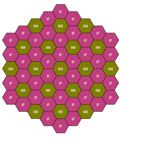
I'm attempting to model an HTGR minicore and having a few issues / sticking points. The core is a simple 2-ring hex grid with a prismatic-like pin lattice Core Pin lattice
Blueprints.yaml
```yaml blocks: fuel: &block_fuel grid name: pins duct: &comp_duct shape: Hexagon material: HT9 Tinput: 600 Thot: 600 ip: 32 op: 32.2 fuel: shape: Circle material: UZr Tinput: 600 Thot: 600 id: 0.0 od: 0.8 latticeIDs: [FP] clad: shape: Circle material: Zr Tinput: 600 Thot: 600 id: fuel.od od: 0.9 latticeIDs: [FP] pitch: shape: Hexagon material: Void Tinput: 600 Thot: 600 ip: 3 op: 3 latticeIDs: [FP, CL] cool pin: shape: Circle material: Graphite Tinput: 600 Thot: 600 id: 0 od: fuel.od latticeIDs: [CL] coolant: shape: DerivedShape material: Graphite Tinput: 600 Thot: 600 assemblies: heights: &heights - 50.0 axial mesh points: &mesh - 2 fuel: specifier : F blocks : &fuel_blocks - *block_fuel height: *heights axial mesh points: *mesh material modifications: U235_wt_frac: - 0.127 xs types : &IC_xs - A systems: core: grid name: core origin: x: 0.0 y: 0.0 z: 0.0 grids: !include minicore-coremap.yaml ```Coremap.yaml
```yaml core: geom: hex symmetry: full lattice map: | F F F F F F F pins: geom: hex symmetry: full lattice map: | - - FP - FP FP - CL CL CL FP FP FP FP FP FP FP FP FP CL CL CL CL FP FP FP FP FP FP FP FP FP CL CL CL CL CL FP FP FP FP FP FP FP FP FP CL CL CL CL FP FP FP FP FP FP FP FP FP CL CL CL FP FP FP ```ARMI 5b7d215 doesn't have any issue running the model and writing a datafile. The output of armi vis-file minicore.h5 yields
gives some spurious messages about the assemblies. I think this also causes the vtu file to not reflect the core geometry, or what I believe the core geometry should indicate
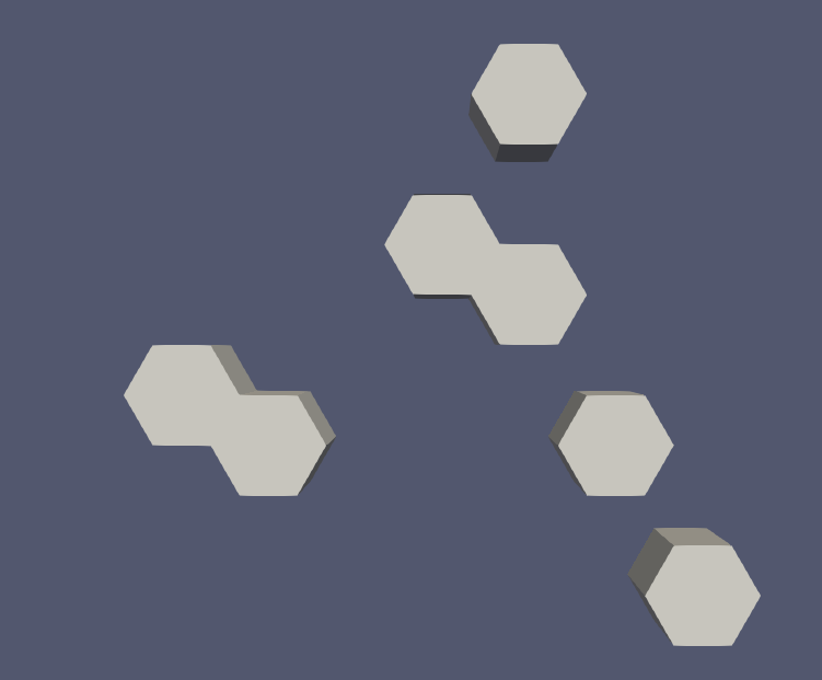
As a note, the current HEAD 1fd21f8236763f43c3bc25b866122aa9789486bc produces similar issues, but with different assembly naming
I've thought about not using the
lattice map
for the pin grid and instead usinggrid contents
which may let me specify the pin position with tuples (ring, pos) if I'm understanding the docs right - https://terrapower.github.io/armi/.apidocs/armi.reactor.blueprints.gridBlueprint.html#armi.reactor.blueprints.gridBlueprint.GridBlueprint.gridContentsAs a consistency check, if you load this reactor up, the fuel lattice appears to be present in each block with the correct lattice structure. Checked based on the
spatialLocator
for circular components in a fuel block.