thainnos / LICSTER

A Low-cost ICS Security Testbed for Education and Research
Other
102 stars 33 forks source link

Questions about the TOBUY list #26

Closed minkione closed 2 years ago

minkione commented 4 years ago

Hi, I am thinking to join this project and start ordering all the parts. Questions:

Overall, I really like your effort of sharing this project! It is definitely a cool one! :)

mniedermaier commented 4 years ago

Hi @minkione,

it would be very nice, if you join our project :+1:

The Conveyor Belt looks running at 24VDC. I cannot see in the to-buy list any power supply. Is the 24VDC power suply included in the kit from fischertechnik?

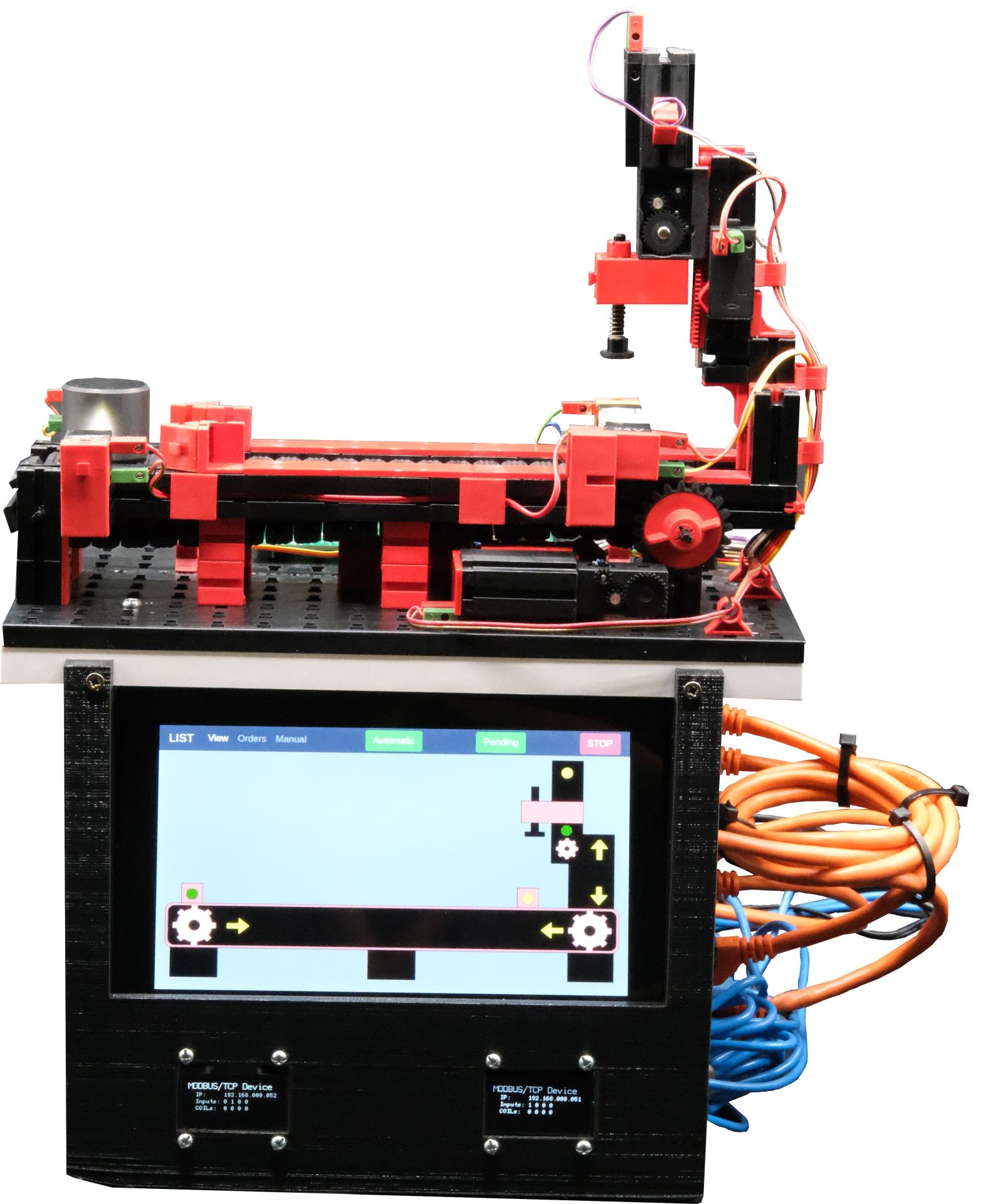
From the image https://raw.githubusercontent.com/hsainnos/LICSTER/master/images/licster.png I see two little OLED screens on the bottom. Those are missing as well in the TOBUY list. Is there anything else that was given as granted?

Thank you very much, I am not sure, why these item are missing. I added 25f3460baf4750f48c8e52f35570d0adabb18d90. I think the basic wiring is very simple. For the PCBs of the remote IOs you will need a soldering iron and basic soldering skills.

I see the wiring/mounting instructions are still missing. Any ETA about some early instructions? (Probably, with all material around, I may be able to connect everything... but some instructions would definetly be beneficial and time saving.)

Currently, we have a group of students, which are working at the project. It was intended, that they make a detailed set-up and wiring guide, but due to the current situation it was not possible, that they have access to the university. But if you want, we can set-up the LICSTER together remote or if you life next to Munich/Augsburg locally.

minkione commented 4 years ago

Thanks for adding the missing items. Do you recall anything else I may need? Asking, cause sometimes I give things as granted... and then new users come back to me asking things that I thought were obvious. But actually was better to precise in the wiki. =)

Overall, I am still on early stage, I guess it will take at least a couple of months before I will be able to assemble it (i.e. holidays, work, ordering/shipping, etc.). But I will definitely come back here in case of issues. For now, I wanted to read the whole repo and see if the project is dead or still alive. And looking at your fast answer, seems doing well 😃

Luckily, I have a quite good lab for assembling/soldering/blowing-up things... so unless rare cases I should be ready to go.

As for the reasons why I would like to join the LICSTER club... that's easy: as the creator of WHID-Injector, WHIDelite [1] and USBsamurai [2] [3] I am always looking for new setups to explain ICS personnel how they work and which are the threats coming from HID devices in an Industrial Plant.

With LICSTER I would be able to easily attack the HMI by using one of those offensive hardware implants. And meanwhile teach how to gather (OS & Network) Forensics artifacts for both postmortem and active defense POVs.

[1] https://www.youtube.com/watch?v=tuoT-cPldMk [2] https://www.youtube.com/watch?v=kmCjYPdNIPM [3] https://medium.com/@LucaBongiorni/usbsamurai-for-dummies-4bd47abf8f87

mniedermaier commented 4 years ago

Your projects and the ideas with the LICSTER testbed sound great!

Thanks for adding the missing items. Do you recall anything else I may need? Asking, cause sometimes I give things as granted... and then new users come back to me asking things that I thought were obvious. But actually was better to precise in the wiki. =)

I know the problem very well... And I also checked our shopping cart again, and added clamps to reduce the soldering effort. I also checked the LICSTER again and hopefully all components are included now.

signal-2020-07-01-121609_003 signal-2020-07-01-121609_002 signal-2020-07-01-121609_001

But I can't promise it for 100%. Until now, too few people have built it and have given feedback. Therefore, I would also find it very nice if you are interested in participating and contributing your experience into the LICSTER community/project.

Overall, I am still on early stage, I guess it will take at least a couple of months before I will be able to assemble it (i.e. holidays, work, ordering/shipping, etc.). But I will definitely come back here in case of issues. For now, I wanted to read the whole repo and see if the project is dead or still alive. And looking at your fast answer, seems doing well smiley

Thanks for your honest feedback. The repo is definitely alive and it will be improved and expanded over the next months. But this takes time... because the project is relatively large. I emphasize here again, I will give as much help as possible at any time!

Luckily, I have a quite good lab for assembling/soldering/blowing-up things... so unless rare cases I should be ready to go.

As for the reasons why I would like to join the LICSTER club... that's easy: as the creator of WHID-Injector, WHIDelite [1] and USBsamurai [2] [3] I am always looking for new setups to explain ICS personnel how they work and which are the threats coming from HID devices in an Industrial Plant.

With LICSTER I would be able to easily attack the HMI by using one of those offensive hardware implants. And meanwhile teach how to gather (OS & Network) Forensics artifacts for both postmortem and active defense POVs.

I looked your projects and these would perfectly fit into LICSTER and maybe it is also possible to make "tutorials" for these kind of attack/attack vectors. Currently we have set-up 6 LICSTERs at our University and we are also using them in different use cases for education, final theses and reasearch.

minkione commented 4 years ago

I was definitely planning to build one LICSTER and meanwhile take photos and eventually a video of the final result. For sure I will keep you updated and make PullRequests once ready. 👍 Thanks for the photos, now I can have a better idea where the boards goes.

The idea was exactly to have LISTER up and running. And subsequently, gather some operational intel, see if I need to tweak either the code or my tools to conduct some attacks and finally, write down tutorials and video demonstrating them.

mniedermaier commented 4 years ago

I was definitely planning to build one LICSTER and meanwhile take photos and eventually a video of the final result. For sure I will keep you updated and make PullRequests once ready. +1

It would be nice to have another fellow soldier here.

Thanks for the photos, now I can have a better idea where the boards goes.

If you have a look at the case, there is everything labeled and pre aligned with the holes: https://github.com/hsainnos/LICSTER/tree/master/devices/case

The idea was exactly to have LISTER up and running. And subsequently, gather some operational intel, see if I need to tweak either the code or my tools to conduct some attacks and finally, write down tutorials and video demonstrating them.

:1st_place_medal: great!

minkione commented 4 years ago

Hi, I will finally start to place orders on Amazon, Mouser,etc. I noticed another thing... the OLEDs should be connected through dupont wires and strip pins. Right? Cause the lcoation of the STM32 boards on the 3D case is not nearby the OLED location on the front panel.

mniedermaier commented 4 years ago

Hi,

I will finally start to place orders on Amazon, Mouser,etc.

Great :+1: . I will help you as much as possible. So always feel free to ask questions :) And maybe we also can improve the documentation together.

I noticed another thing... the OLEDs should be connected through dupont wires and strip pins. Right? Cause the lcoation of the STM32 boards on the 3D case is not nearby the OLED location on the front panel.

It is correct, that the OLED screens are not mounted on the PCBs of the remoteIOs. For testing purpose I have used dupont wires, but i would recommend to solder the wires for long term usage (The cables are already on the ordering list https://amzn.to/37hDE4H ).

displayWiring

minkione commented 4 years ago

What is this part? https://github.com/hsainnos/LICSTER/tree/master/devices/spare_parts/goods

Do I need to print it too or is just some non-functional stand?

mniedermaier commented 4 years ago

it is only a spare part (this is the cylinder, which moves on the convey belt...). You do not need it, if you do not lose your cylinder/goods :)

minkione commented 4 years ago

Hallo again :)

Having said that I am still reading around the repo... I started gathering some of the static IPs set on each RPi, in order to create an Architectural Diagram. Probably based on this https://raw.githubusercontent.com/hsainnos/LICSTER/master/devices/plc/images/list-network.png and place it on the main README somewhere, for ease of access.

One thing I am missing... I see only one STM32 IP: 192.168.0.50... Did I miss the other?

SCADALTS 192.168.0.10 HMI 192.168.0.20 PLC 192.168.0.30 STM32-A 192.168.0.50

P.S. I just realized that the SNORT server is deployed on the 4th RPi (which I didn't add to my Amazon order), Would be wise to add it to the main shopping list (maybe as optional purchase, but still worth to keep all needed material in one single place).

minkione commented 4 years ago

As I said, I am still reading around :D Just found this page: https://github.com/hsainnos/LICSTER/blob/2a5bb16f5d8cfa284506e3c2e0270a67a794a079/network_captures/README.md

In here though I see some inconsistencies about STM32 IPs...

Devices with IPs

Device IP MAC
Remote IO 1 192.168.0.51 00:80:e1:00:00:01
Remote IO 2 192.168.0.52 00:80:e1:00:00:02
PLC 192.168.0.30 b8:27:eb:bc:a0:b1
HMI 192.168.0.20 b8:27:eb:fe:6b:a8
SCADA 192.168.0.10 b8:27:eb:f7:33:32
Switch 192.168.0.1

Which is the right one 192.168.0.50 as per the example in https://github.com/hsainnos/LICSTER/blob/master/devices/remote_io/software/README.md or the 192.168.0.51?

mniedermaier commented 4 years ago

One thing I am missing... I see only one STM32 IP: 192.168.0.50... Did I miss the other?

The IPs are set trough the Resistors for remote IO1 (R31, R34, R38, R40, R42) and for remote IO2 (R32, R33, R38, R40, R42) on the custom PCB. If no PCB is attached the IP address of the remote IO is 192.168.0.50 (This is the IP address for testing the functionality without any additional PCB).

P.S. I just realized that the SNORT server is deployed on the 4th RPi (which I didn't add to my Amazon order), Would be wise to add it to the main shopping list (maybe as optional purchase, but still worth to keep all needed material in one single place).

In my opinion, the projects are "independent" from the regular LICSTER set-up, because some projects are expanding the testbed. We are also currently have a project, where we want to replace the OpenPLC with a Siemens S7-1200. For the project with snort, also a Virtual Machine or something like this could be used for this. But I think you are right and I/We have to give an overview, which additional things could be bought for different projects/extensions.

minkione commented 4 years ago

I agree on keeping LICSTER and side projects indipendent, but since the Snort one is merged in this repo, I thought to rather better mention the needed RPi in the buy list as optional, than avoid surprises later.

As for the S7... may I ask why that PLC choice? Cause is the most commonly used in PROD? I was thinking about it too (since is indeed the most known) thouse I was thinking to pick one that is known to have a good amount of vulnerabilities and related PoCs, in order to expand the number of available attackers scenarios on the testbed. Also Omron, Allen-Bradley, Schneider, may have known vulnerable PoCs publicly available and reproducible (i.e. random example to get to the point https://github.com/thiagoralves/EtherSploit-IP ).

Again... take this as "throwing random thoughts/ideas for brainstorming" and not as feedbacks nor critics.

minkione commented 4 years ago

Would be wise to add the paper somewhere too in the repo.

https://arxiv.org/pdf/1910.00303

mniedermaier commented 4 years ago

I agree on keeping LICSTER and side projects indipendent, but since the Snort one is merged in this repo, I thought to rather better mention the needed RPi in the buy list as optional, than avoid surprises later.

Maybe it would also be a possibility to create branches for the different projects. I will think about some solutions :)

As for the S7... may I ask why that PLC choice? Cause is the most commonly used in PROD? I was thinking about it too (since is indeed the most known) thouse I was thinking to pick one that is known to have a good amount of vulnerabilities and related PoCs, in order to expand the number of available attackers scenarios on the testbed. Also Omron, Allen-Bradley, Schneider, may have known vulnerable PoCs publicly available and reproducible (i.e. random example to get to the point https://github.com/thiagoralves/EtherSploit-IP ).

There is no technical reason for this decision. However, I currently have an S7 1212 with firmware version 2.0 lying around, which is also vulnerable to a lot of attacks. Siemens is also widely used in Germany, which of course makes it attractive for us. But the Structured Text code should be usable on any device, which supports ST.

Again... take this as "throwing random thoughts/ideas for brainstorming" and not as feedbacks nor critics.

Please always give us feedback and I also love to discuss and discover new opportunities that I haven't thought of myself.

Would be wise to add the paper somewhere too in the repo. https://arxiv.org/pdf/1910.00303

I have cited it on the bottom of the Readme https://github.com/hsainnos/LICSTER/blob/master/README.md . But I also have to say, that the LICSTER project has evolved since this publication :) So I hope all necessary information are in the GIT.

I have started with a set-up on my desk (see image below), with a very basic software implementation... then we continued with a wooden construction and a more advances software... and now we have a nice 3d printed cube with a good software base :+1: , which of course can and hopefully will be further optimized.

firstSetup

minkione commented 4 years ago

update: Finally got all the stuff. Now I need to organize my spare time to start :) Will keep a diary with notes and photos.

mniedermaier commented 4 years ago

I am really looking forward to your experiences and feedback. If you need help, we can also do a video call. We will definitely do this!

minkione commented 4 years ago

Note to myself to keep everything in one place: image

mniedermaier commented 4 years ago

Hello minkione,

I hope you make progress with assembling the LICSTER? Does everything work so far, except the PLC image?

If you need help or want to video chat, we can do that.

We are currently working on OPC-UA for LICSTER, as well as other projects such as IDS, some of which can already be seen on the GIT. I am also interested in further discussion and ideas, how we can improve and extend the testbed.

minkione commented 4 years ago

Hi, I have started today re-reading the documentation and started figuring out the steps to assemble everything. Reason why of my note here :) So far the plan is: 1) Bake the uSDcards and check if all RPis work 2) Assemble the HMI TFT-touch monitor 3) Assemble PCBs while keeping in mind how to solder the Resistors depending on PCB1 & PCB2 addresses. 4) Figuring out the correct wiring between the punching I/O-motherboard and the Nucleos. (guess this should be enough https://github.com/hsainnos/LICSTER/blob/master/devices/remote_io/README.md#wiring) 5) Wiring the OLED Screens 6) Flashing the Nucleos 7) All-together 8) Sacrifice couple of goats to random Gods 9) Switch everything on and see what I missed :D

minkione commented 4 years ago

Guten Morgen! Question: Which is the correct value of R3~R6? 0ohm or 10Kohm? image

minkione commented 4 years ago

Note for LEDs orientation: image

mniedermaier commented 4 years ago

Guten Morgen!

Nice :+1: Buongiorno

Question: Which is the correct value of R3~R6? 0ohm or 10Kohm? image

It is like in the schematics. The resistors R3-6 should have about 10k or a (bit) bigger. R44, R43, R26 and R25 should have about 1.5k or (bit) lower.

image

Important is, that this is a voltage divider, which divides the input voltage of 24V from the sensors to less then 3.3V for the STM32 microncontrollers.

https://ohmslawcalculator.com/voltage-divider-calculator

minkione commented 4 years ago

Clear. those dividers are acting as level shifters. 👍

Out of curiosity... why in the photo 0ohms were used and no level shifters? image

minkione commented 3 years ago

Hi , I am planning to continue soldering the PCBs later in the evening. Wonder why in the photo above there were not level shifters installed. Was an experimental board?

mniedermaier commented 3 years ago

Wonder why in the photo above there were not level shifters installed. Was an experimental board?

I have searched for level shifters from 3.3V to 24V, but did not find some for a appropriate price. Do you have a recommendation for a level shifter. Maybe we could replace this in a future revision. Thanks and regards.

minkione commented 3 years ago

Sorry for the misunderstanding. With "level shifters", I meant the set of resistors that are used as ghetto-style level shifters. In the schematics is visible that the R3-R6 are 10k and R25-26-43-44 are 1.5k. Though, in the photo in the wiki... those Resistors are all 0ohm or not populated.

Why straight connection was used (i.e. by using all 0ohm components). It doesn't reflect the schematics. Got my point? This inconsistency between schematics and image in the wiki may create confusion.

image

image

mniedermaier commented 3 years ago

Yes, you are right. I opened a new issue and I will fix this with the next LICSTER I will set-up. The schematics are correct.

minkione commented 3 years ago

Perfect. I will keep baking the two PCBs, then make a bath with the ultrasonic cleaner. And make some photos of it with proper labels PCB1 / PCB2 in order to highlight their differences. (i.e. R30ish resistors for board selection) 👍

minkione commented 3 years ago

PCBs done 👌 IMG_0407 IMG_0406

mniedermaier commented 3 years ago

looks very nice! great work! Have you already flashed the stm32 boards, and looked if the OLED displays are showing something?

minkione commented 3 years ago

Yup, all good. flashed 
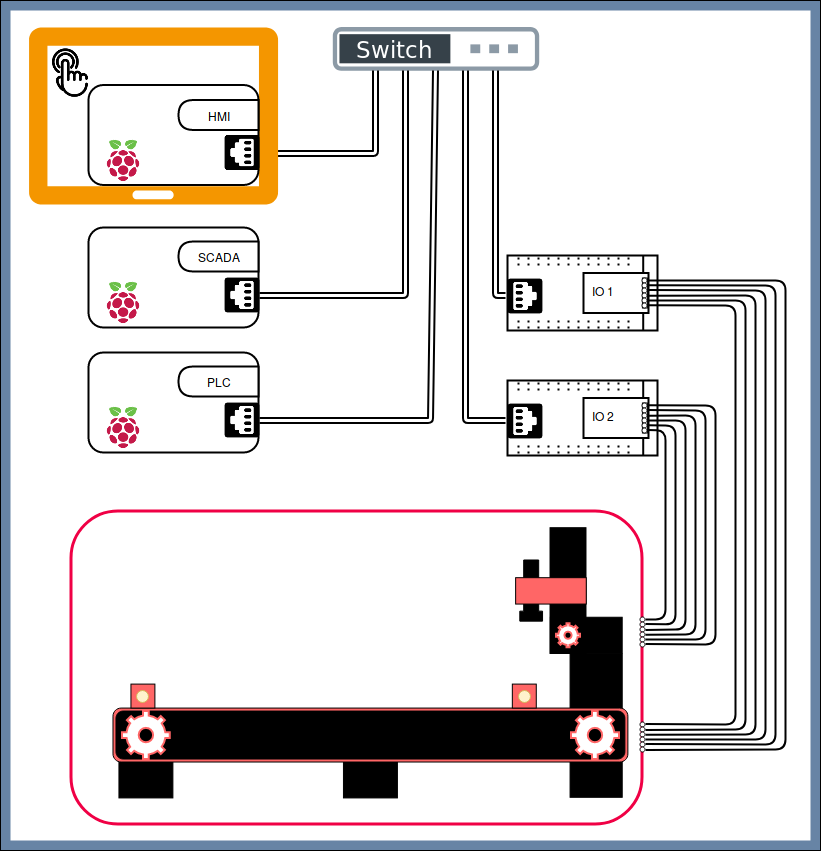
Next step will be connecting them to the I/Os of the conveyor-belt's mainboard: https://github.com/hsainnos/LICSTER/tree/master/devices/remote_io#wiring

mniedermaier commented 3 years ago

This looks perfekt!

https://github.com/hsainnos/LICSTER/tree/master/devices/remote_io#wiring

Is this table self explaining? I was not sure how to make the wiring as easy as possible, if you have any recommendation on this, let us know.

minkione commented 3 years ago

Yeah is not the most intuitive scheme for wiring I have seen, but I guess I got the point. 👍

To be sure... F1, RIO1-1, RIO2-1 are all connected to 24V power supply. Correct?

I think, once the wiring will be tested, I will draw something with Fritzing to make all connection dumb-proof clear.

Side note... In the Fischertechnick I see that P1 & P2 are VCC 24V. And P3 and P4 are both GND. It looks like there are 2 separate power rails (i.e. one for sensors and one for actuators. What a weird decision from Fischertechnick). That's why all VCC and GND are connected?

image

mniedermaier commented 3 years ago

I think, once the wiring will be tested, I will draw something with Fritzing to make all connection dumb-proof clear.

Yeah this will make sense. I have never done this... Maybe I also will have a look at

F1, RIO1-1, RIO2-1

minkione commented 3 years ago

Oh oh oh, Merry Xmas! 🎅 (Sorry, I am already in the xmas mood. :D)

Guten morgen, After a never-ending gig at work I finally managed to get some time for LICSTER. Can you have a look at these videos I recorded? https://mega.nz/folder/aRJSlDTD#M-zuZN0VVYTc7ZOQarvdZQ To me looks like something is pulling-up (i.e. 24V?) all the components on the Fischetechnick.

I double-checked the wiring and are matching the documentation. Is there a particular order I should initiate all RPis?

mniedermaier commented 3 years ago

Hello @minkione,

in gneral, this looks good. I only had a short look at the videos, because I have no sound on the device where I am currently working on (will have a more detailed look tonight). My suggestion is to go to the HMI, you can test the control on the 'manual' (login is 1234) tab and also can check the sensors in the overview tab. With this, you can check if the wiring is correct and the signals arrive at the remote IOs. Have you already checked this possibility?

Is there a particular order I should initiate all RPis?

No just power everything at the same time. They will boot up correctly.

Thanks and merry Christmas

minkione commented 3 years ago

Let me know once u will be able to hear the audio too. U will understand what's wrong.

After lunch I'll try check from the HMI as u suggested.

mniedermaier commented 3 years ago

Hi @minkione,

sorry for the delayed response. I watched your videos in detail. This is a very strange behavior, especially the input switching from 0/1. Have you had time to test, if you can control your setup via the HMI? Can you also check, if on the STM32 board the input signals are detected from the sensors? Furthermore, do you have a volt meter? Can you check the output signals of the stm32 boards?

Thanks and happy christmas

minkione commented 3 years ago

Hi, Can you also check, if on the STM32 board the input signals are detected from the sensors? How I can check? Do you mean through the UART of the STM32 board? Or by other means?

Furthermore, do you have a volt meter? Can you check the output signals of the stm32 boards? Yes, I can also check with the Oscilloscope.

As I understand... those that input switch 0/1 is a PLC coil, right? That for uknown reasons is quickly switching from 0 to 1. Correct? Here's my plan:

Let's see how it goes. 🤞

mniedermaier commented 3 years ago

Hi @minkione,

I would do the following. The start parameter of the LICSTER process is, when the left light barrier is active/interrupted, e.g. by the cylinder. So the start condition is achieved, when the Remote IO 1 licster

In this case, the remote IO1 (192.168.0.51) should show on the inputs: 1 0 0 0 and on the outputs: 0 0 0 0

Checking inputs basic setup:

  1. Switch everything on at the same time (e.g. connect everything to one power strip)
  2. If there is any odd behavior remove the output wires between remoteIOs and the fischertechnik
  3. Check if the inputs of remote IO1 get identified by looking at the small display on the remoteIOs
  4. Check if the two sensors on the conveyor belt are working by interrupting the light barrier on the conveyor belt
  5. Check if the communication between remote IO1 and the PLC/HMI is working by checking if the sensor changes result in changes on the HMI
  6. Do the same with IO2 and the sensors on the stamp machine

Checking outputs basic setup:

  1. Switch everything on at the same time (e.g. connect everything to one power strip)
  2. Go to the HMI and login to manual... The pin is 1234 at default
  3. Try to move the conveyor belt and the stamp machine
  4. If the commands are mixed, adjust the wiring

If this steps do not result in finding the error, I would start with the voltage meter. Does this helps you? Please send me your feedback and hopefully your results.

We will get this working! Go on :)

minkione commented 3 years ago

Few steps forward. https://mega.nz/file/rBpymaqB#q7821ZZfDBBc6nS-L327asMza9_jSoQSVri00SUrMTE

minkione commented 3 years ago

LOL Another component was not acting nice... this time Q4 of RIO2. Replaced and now the belt works. https://t.co/PNb5vP375a?amp=1 Now just the floating punch switch down to resolve. I bet is yet again a faulty component.... let's see.

Wonder why... ok I am too lazy to wear ESD bracelet... but never happened before such sum of unfortunate events while dealing with PCBs... well.. glad I am resolving these problems one by one.

minkione commented 3 years ago

as expected, the floating behaviour was due the pull-down resistor 1.5K on Pin7. Fixed. Now I need to figure out last thing. Why the belt moves twice further on one side respect the other. Will check the code first this time. I get is due the PWM pulse difference. But need to check to be sure

minkione commented 3 years ago

Ok, The codebase for the STM32 is way too massive and the commits are not helping to figure out where I should dig. My bet is that either there is a pulse difference between BELT-BACKWARD & BELT-FORWARD commands defined within the STM32 sources... or that the photo-sensor Pin5/RIO2-8 is sending the logic 0 signal through MODBUS to the HMI with a delay (which I doubt is the issue).

Video with audio as reference: https://mega.nz/file/OQwhiKRY#tLNVT8zxNbD5gNHwe-ie53IPitf0q1loHtPk54bQKJE

Could you please point me to the right part of the STM32 codebase where I can see how you handle/drive the belt? Thanks!

mniedermaier commented 3 years ago

Looks good and sounds nice. I watched your videos and in general it looks good.

The behavior wit the conveyor belt moving twice as long to the left isn't a problem of our set-ups. So i think and hope it is not a software problem in general. Maybe this is also a problem of the output circuit on your remoteIO1 board? I think with this long delay in moving left the automatic program will fail. But you could test to put the cylinder on the start position and make an order. Maybe you already have tried this?

mniedermaier commented 3 years ago

The stm32 are 'dump' devices, they are running a modus slave on port 502 and waiting for modbus commands from the PLC. So the sensor values are read by the PLC and the modbus commands are also send by the PLC. The process is controlled by the ST program: https://github.com/hsainnos/LICSTER/blob/master/devices/plc/data/machine.st

In my opinion it is a hardware problem... Because on all LICSTER the same software is running from the images i provided... But of course, there could be any problem with the software...

minkione commented 3 years ago

At last... IT WORKS! It was a cold joint UNDER an SMT component. Not visible even with microscope from top. The best part of it is that was kinda touching. That's why it was still working but with some glitches. Now everything works. Phew... was a looong day. Thanks man for the support!

Next phase.... fitting everything in the case and start working on docs.

mniedermaier commented 3 years ago

THIS IS AWESOME!!!!!

Makes me really happy, that everything works now! You had a very long and hard way to go. Beside this, I hope you already leraned a lot and could also enjoy the project so far.

Next phase.... fitting everything in the case and start working on docs.

Please keep us/me in the loop. Have a nice weekennd

minkione commented 3 years ago

Aloha! I am trying to figure out how all components are mounted on the 3D printed case. I noticed one thing... the STM32 boards haave the mounting holes too to the pin-headers thus the M3 screws/bolt have some difficulties to fit in especially once the STM32 boards+duaghter-PCBs are stacked one over each-other.

Whenever u'll have time... can u please make couple of closer photos? Thanks!